VISTAP Security System pdf manual download. Also for: Vistapul.
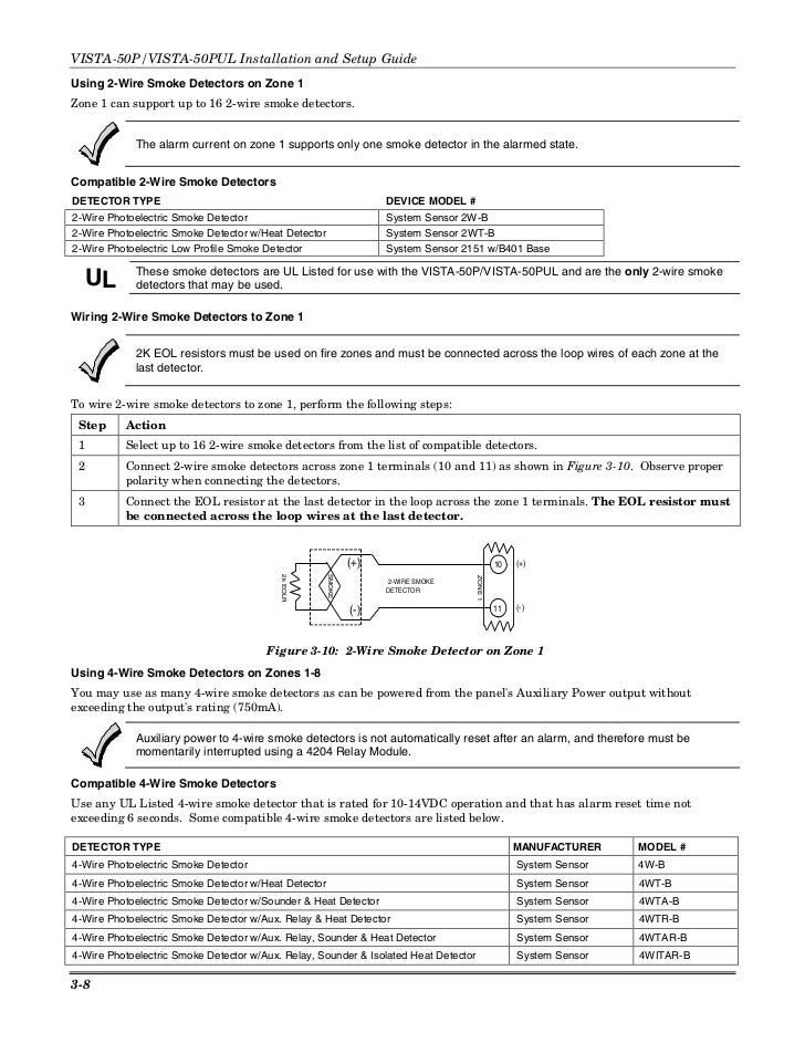
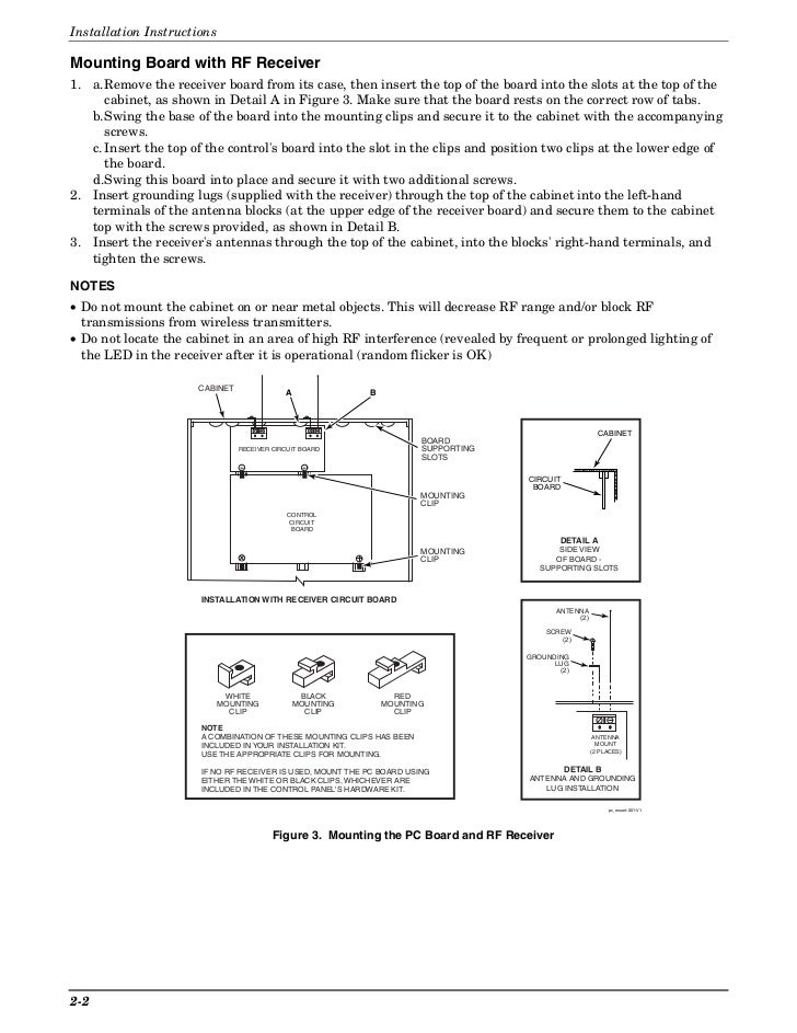
27 Wiring 4-Wire Smoke Detectors to Zones . Installing the Control’s Circuit Board Refer to the diagram below when mounting the PC board.
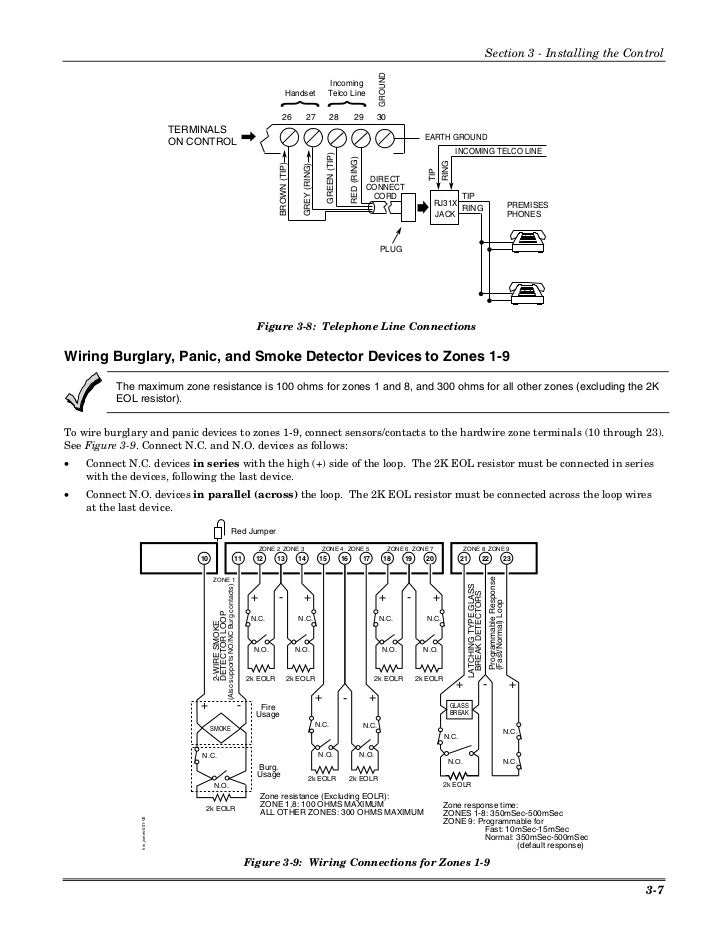
• Hang the three . This includes panel connections, RPM connections, and field wiring.
6. Verify that the zone The VistaP and higher controls do not have the *86 option.
The First Alert FA .. diagram below. If any wire attached to the. SUMMARY OF CONNECTIONS DIAGRAM programming options, see the VISTAP/VISTAPUL INSTALLATION INSTRUCTIONS.
Use the VISTAPADT/PADTUL PROGRAMMING FORM beginning on See Installation Instructions for wiring instructions. *Door sticker for 50P- Wiring diagram sticker (or can?? lid??) *Keypad wiring harness (I have one from a that works, but now I don’t.

VISTAP Security System pdf manual download. Figure Wiring a PRM using a and a Power Supply ..
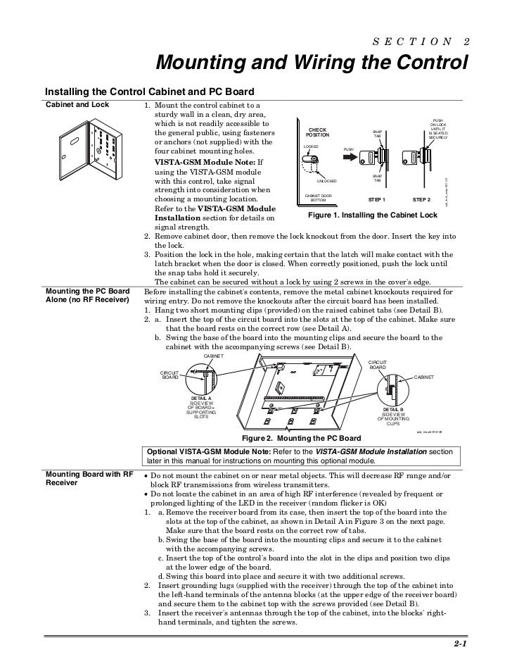
using a modem or telephone line by using a of Connections diagram on the inside back cover of this .programming options, see the VISTAP/VISTAPUL INSTALLATION INSTRUCTIONS. • Make sure that one two-line alpha keypad is connected to the control and is set to device address “” Single Partition System •The system default is for a single partition system.
Use the VISTAPADT/PADTUL PROGRAMMING FORM beginning on page 7. The VISTA is a microprocessor-based state-of-the-art security control intended for wireless as well as wired zone applications.
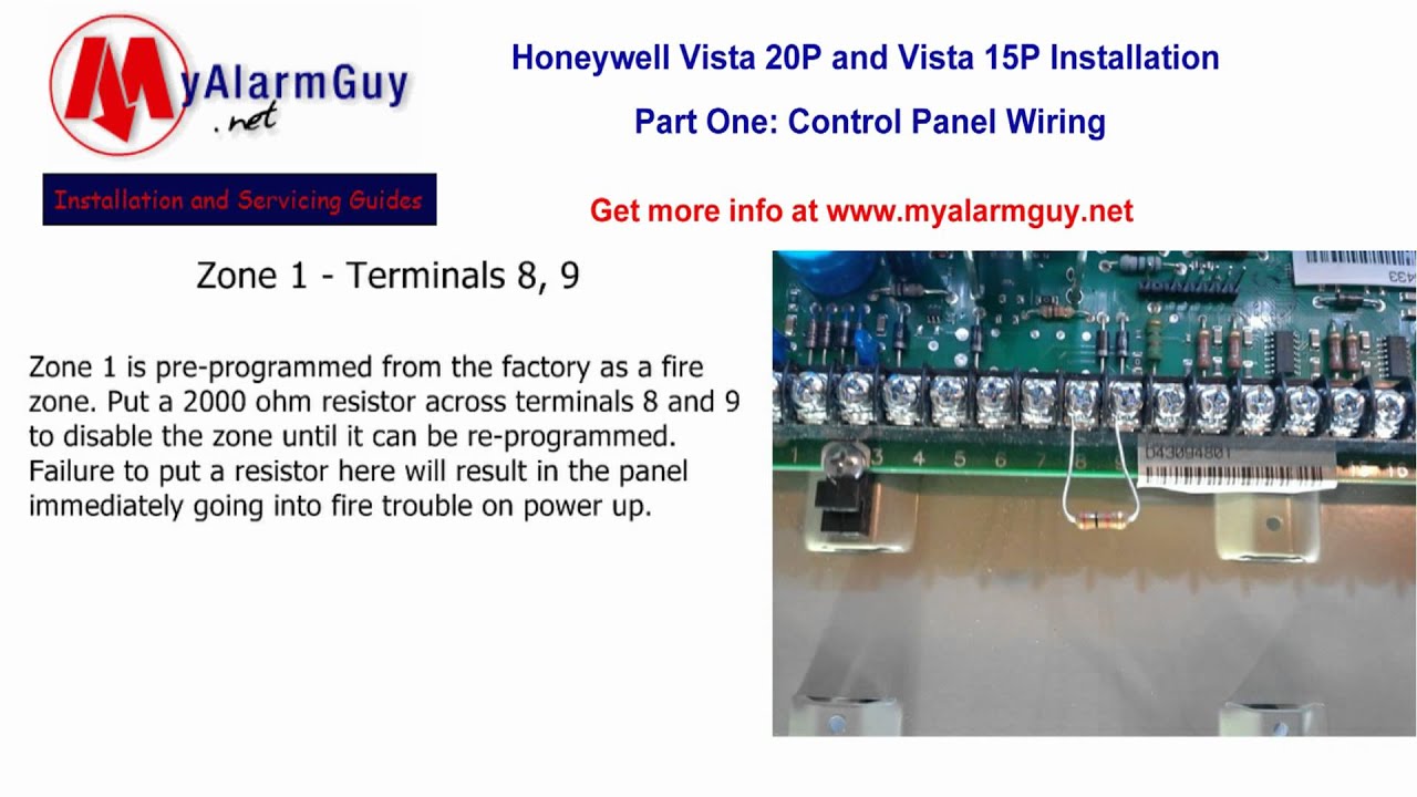
Supports up to 22 zones, in the following configuration: 6 hard wired EOLR “basic” zones. “ Up to 16 RF expansion zones by using an appropriate type RF receiver (up to 8 with type). Refel.
Thanks for using Alarm Grid as a resource. to the cabinet’s right side wall as shown in the diagram below, and wire it to one of the hardwire zones.
terminal wiring, or between the Bell (+) terminal wiring and earth ground. The VISTAP/VISTAPUL indicates the trouble condition regardless of whether the system is armed or disarmed.
Section 1: GENERAL DESCRIPTION The VISTAP is an 8-Partition alarm control panel that supports up to 86 zones using basic hardwired, polling loop, and wireless zones. In addition, the control offers relay control and scheduling capabilities for automating system functions.
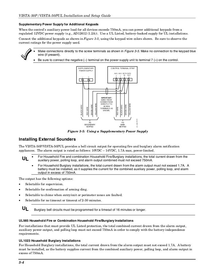
Refer to the Wiring Diagram on the reverse side for connection information. NOTE: This system uses a range of reserved addresses for each type of device.
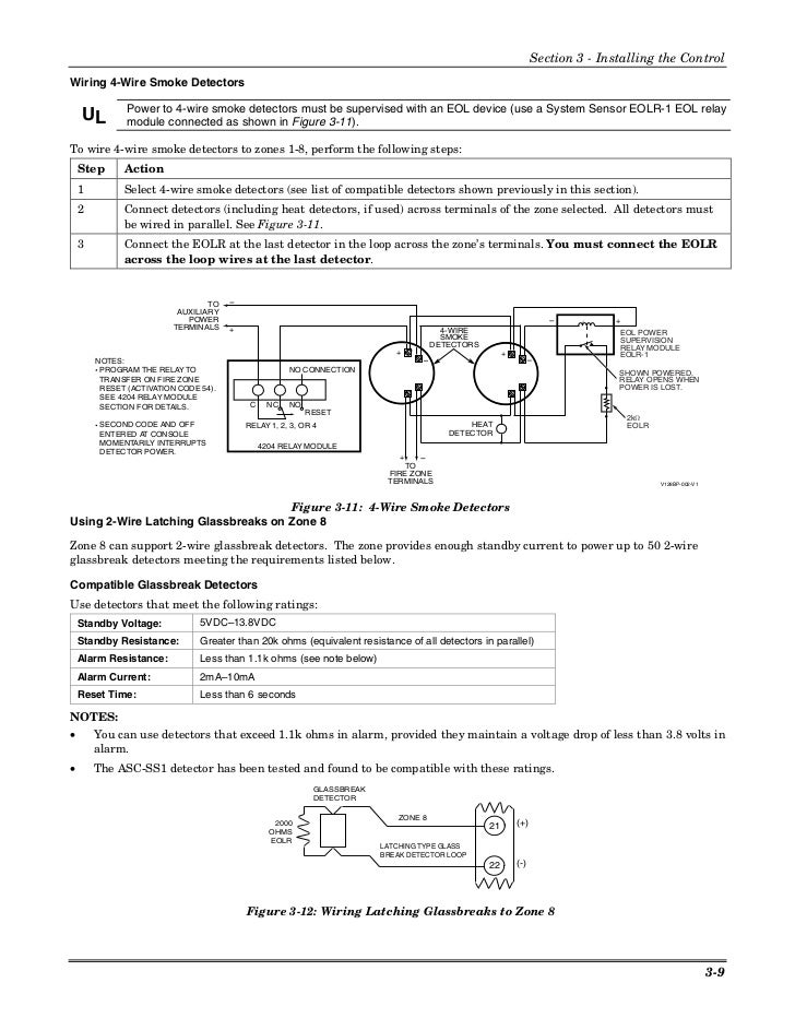
1. Connect keypads and other addressable devices to the ECP terminals Refer to the wiring chart below for wire sizes and maximum wire run lengths.ADEMCO VISTAP INSTALLATION INSTRUCTIONS MANUAL Pdf Download.Ademco Vista 20P Wiring Diagram
