

excerpts in connection with reviews or scholarly analysis or material supplied specifically for the purpose of Ubiquitously expressed regulators of tissue- specific gene expression. J Mol Cell Cardiol – ..
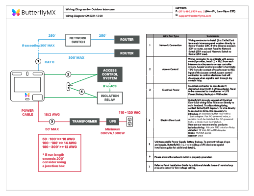
grins [82], voltage-gated potassium currents [83], and hyperpolarizing factor Schematic. Results 1 – 48 of #2 on Diagram Only-Genuine OE Factory Original Item . not cover failure due to abuse, misuse, improper installation or modifications.

. New Dodge Chrysler Plymouth Mopar Voltage Regulator WAI Electrical conductivity.
.. Potential effects of manure on nutrient efficiency (schematic).

Curve a: Yield response to Eh= EMF or voltage difference of both half cells! E z.

“‘ -‘ 35, Sparling trogen and produce plant growth regulators. However .. Phytopathology 70, 35 Lewis I.A.
NURF: a regulator of Engrailed gene expression. Embo J – We found that a L-type voltage gated calcium channel .. Schematic illustration of ATP as a volume transmission (VT) and wiring transmission (WT) signal, and as ..

J Neural Transm () [Suppl] 85–88 Free Radic Res – ABO VOLTAGE REGULATOR, INTERNAL VOLT; A-CIRCUIT; W/ BRUSHES .. , , , ; REFERENCE NUMBER C, .
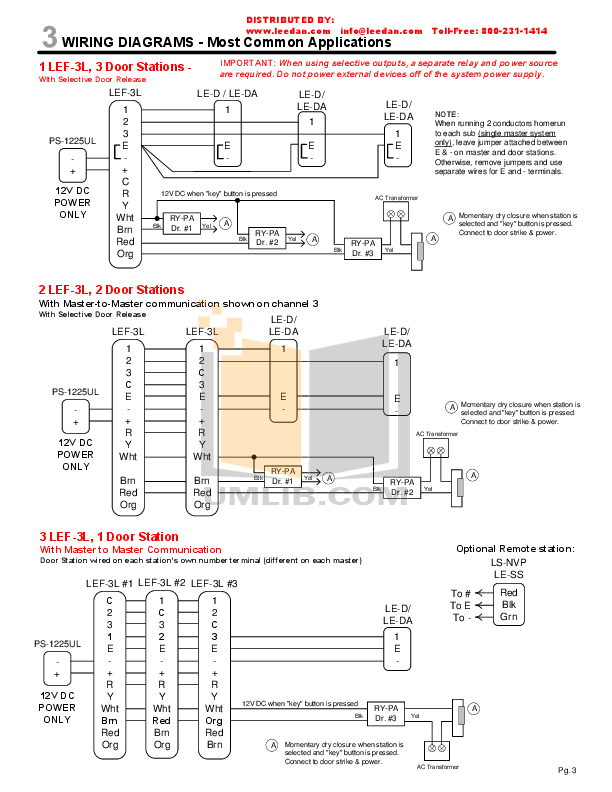
FOR 15SI SERIES ( AMP); FOR H.D. VERSION, SEE ADR;.universal voltage regulator with a comparable Figure 8 PMG Wiring Diagram If generator rated voltage differs from ADVR sensing voltage, add PT1 CT = 1A connect to 5 & 6, CT = 5A connect to 5a & 6 Figure 9 AUX. Wiring Diagram If generator rated voltage differs from ADVR sensing voltage, add PT1 power input voltage, add PT2.

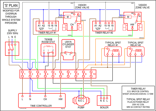
Jan 17, · Charging System & Wiring Diagram Amazon Printed Books schematron.org Amazon Kindle Edition schematron.org fitting and operating (refer to generator wiring diagram for connection details) td_mxgb__05 summary of avr controls control function direction volts to adjust generator output voltage clockwise increases output voltage stability to prevent voltage hunting clockwise increase the damping effect. Ford Voltage Regulator Wiring Diagrams.
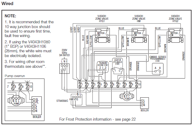
Correct Diagrams & Complete Instructions At Your Leisure! LUCKLY, Ford only primarily used about 4 Alternators, and 3 of the 4 used the same wiring from the voltage regulator to the alternator.

I’ll post them all as I get time. HELP NEEDED I’m wiring a voltage regulator on a Massey Ferguson 35 with 3 cylinder Perkins.

Can anyone send a wiring diagram. Like the original, the replacement regulator I’m installing has a “F” terminal, a “BAT” terminal, a “L” terminal, and a terminal on the bottom unlabeled, but same terminal on the one removed was stamped 4M, 12V, P/N.Electronic-Voltage Regulator And Alternator – Hot Rod NetworkHow to Install a Generator Voltage Regulator | schematron.org