
When it comes to controlling the volume of audio signals in an electronic circuit, a volume potentiometer, also known as a volume control, is often used. It allows the user to adjust the volume level of a sound source, such as a microphone or a speaker, to their desired level. In this article, we will discuss the basic wiring diagram of a volume potentiometer and how it functions in an audio circuit.
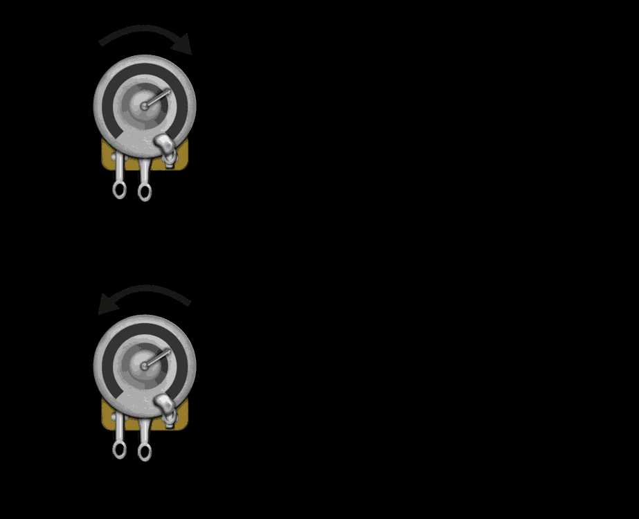
A volume potentiometer usually consists of a shaft attached to a resistive element and a movable wiper that slides along the resistive element. By rotating the shaft, the wiper makes contact with different parts of the resistive element, changing the resistance between the wiper and the end terminals. This change in resistance alters the volume level of the audio signal passing through the potentiometer.
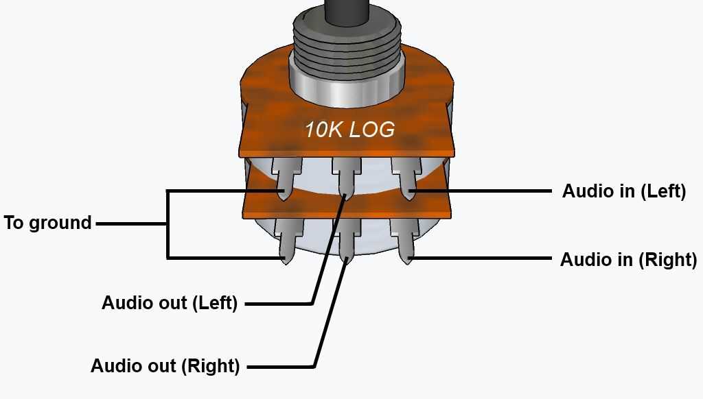
The wiring diagram of a volume potentiometer typically includes three terminals: an input terminal, an output terminal, and a ground terminal. The input terminal is connected to the audio signal source, such as a microphone or a line input. The output terminal is connected to the audio amplifier or the audio output device, such as a speaker. The ground terminal is connected to the common ground of the circuit, providing a reference point for the audio signal.
What Is a Volume Potentiometer?
A volume potentiometer, also known as a volume control or volume knob, is a type of electrical component used to adjust the sound level of an audio device. It is commonly found in audio systems such as amplifiers, stereos, and musical instruments.
A volume potentiometer typically consists of a circular knob attached to a shaft, which is connected to a variable resistor. As the knob is turned, the shaft rotates and adjusts the position of a wiper along the resistor, changing the resistance value. This, in turn, modifies the volume level of the audio signal.
The most common type of volume potentiometer is the logarithmic or audio taper potentiometer. This type of potentiometer is designed to provide a smooth and gradual change in volume, with smaller adjustments near the lower volume levels and larger adjustments near the higher volume levels. This logarithmic taper allows for finer control of the sound level, as human perception of loudness is not linear.
Volume potentiometers are typically wired in a circuit between the audio source and the amplifier or output device. The potentiometer’s resistance is connected in series with the audio signal, and the wiper is connected to the amplifier input. By adjusting the knob, the user can change the amount of signal that is sent to the amplifier, thereby controlling the volume of the audio output.
In addition to volume control, some potentiometers may also include other features such as balance control or tone control. These additional functions allow for further customization of the audio output, allowing the user to adjust the left-right balance of a stereo signal or modify the frequency response of the sound.
Overall, volume potentiometers play a crucial role in audio systems by providing the user with a simple and intuitive way to adjust the volume of their audio devices. Whether in a home entertainment system or a professional audio setup, volume potentiometers help to optimize the listening experience and ensure that the sound level is just right.
Understanding the Basics of a Volume Potentiometer
A volume potentiometer, also known as a volume control or pot, is an essential component in audio systems. It is a variable resistor that controls the output volume of an audio signal by adjusting the resistance value.
How Does a Volume Potentiometer Work?
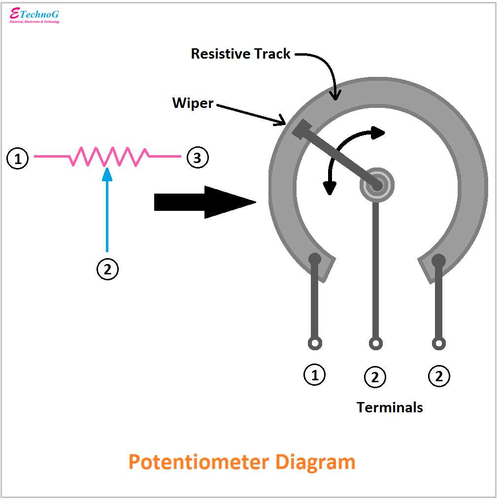
A volume potentiometer consists of three terminals: the input terminal, the output terminal, and the wiper terminal. The input terminal receives the audio signal, while the output terminal sends the adjusted signal to the amplifier or speaker. The wiper terminal is connected to a movable contact that slides along the resistive element, changing the resistance value and thus altering the volume of the signal.
Wiring Diagram
To wire a volume potentiometer, you will typically connect the input terminal to the audio source, such as a CD player or microphone, and the output terminal to the amplifier or speaker. The wiper terminal is then connected to the amplifier or speaker as well, so that the adjusted signal can be sent for amplification or output.
Adjusting the Volume
To adjust the volume, you simply turn the knob or slider on the potentiometer. As you do so, the wiper terminal moves along the resistive element, changing the resistance value and thereby increasing or decreasing the volume of the audio signal. The resistance value can vary from zero to the maximum resistance value of the potentiometer.
Applications of Volume Potentiometers
Volume potentiometers are used in various audio devices, including amplifiers, mixers, radios, and musical instruments. They allow users to control the volume levels and find the desired sound level for their listening pleasure or performance needs.
In conclusion, understanding the basic operation and wiring of a volume potentiometer is essential for anyone working with audio systems. By adjusting the resistance value, a volume potentiometer enables precise control of the signal’s volume, enhancing the user’s listening experience or performance output.
Wiring Diagram for a Volume Potentiometer
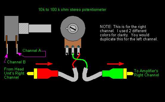
A volume potentiometer, also known as a volume control or pot, is an electronic component used to adjust the volume of audio signals. It is commonly found in audio devices such as amplifiers, radios, and musical instruments. The wiring diagram for a volume potentiometer illustrates how the potentiometer is connected in a circuit to control the volume of the audio signal.
In a typical wiring diagram for a volume potentiometer, there are three main connections: the input, the output, and the ground. The input connection is where the audio signal enters the potentiometer, usually from the audio source or amplifier. The output connection is where the adjusted audio signal is sent out, usually to a speaker or another audio device. The ground connection is used to provide a reference point for the circuit and ensure proper grounding.
Typically, a volume potentiometer consists of a resistive element and a wiper. The resistive element is a long, coiled wire which acts as a voltage divider. The wiper is a movable contact that slides along the resistive element, allowing the user to adjust the amount of resistance and therefore the volume of the audio signal. The wiring diagram shows how the wiper is connected to the input and output connections, as well as the ground connection.
It is important to note that the wiring diagram for a volume potentiometer may vary depending on the specific circuit and components being used. Different potentiometers may have different numbers of terminals, and the connections may need to be adjusted accordingly. It is always recommended to refer to the manufacturer’s instructions or datasheet for the specific potentiometer being used to ensure proper wiring.
Step-by-Step Guide on Wiring a Volume Potentiometer
When it comes to wiring a volume potentiometer, there are a few key steps to follow in order to ensure a successful installation. Here is a step-by-step guide to help you through the process:
Step 1: Gather the necessary materials
Before you begin wiring the volume potentiometer, make sure you have all the necessary materials on hand. This includes the potentiometer itself, wire strippers, soldering iron, solder, and any additional wiring or components required for your specific setup.
Step 2: Determine the value and type of the potentiometer
It is important to know the value and type of potentiometer you are working with before wiring it. This information can usually be found on the potentiometer itself or in the product documentation. Common potentiometer types include linear and logarithmic, and they come in various resistance values.
Step 3: Identify the lugs of the potentiometer
Most potentiometers have three lugs or terminals: input, output, and ground. The input and output lugs are usually located on one side of the potentiometer, while the ground lug is often found on the opposite side.
Step 4: Strip the ends of the wires
Using wire strippers, carefully strip the ends of the wires that will be connected to the potentiometer lugs. Make sure to strip only a small portion of the insulation to avoid any short circuits.
Step 5: Connect the wires to the potentiometer lugs
Start by connecting the input wire to the input lug of the potentiometer, the output wire to the output lug, and the ground wire to the ground lug. If necessary, refer to the potentiometer’s documentation or a wiring diagram for guidance.
Step 6: Secure the connections

Once the wires are connected to the potentiometer lugs, you will need to secure the connections. This can be done by soldering the wires to the lugs, ensuring a strong and reliable connection.
Step 7: Test the volume potentiometer
After the connections are secure, it is important to test the volume potentiometer to ensure it is functioning properly. Connect the potentiometer to the audio system or device it will be used with, and adjust the volume to test its effectiveness.
Following these steps will help you successfully wire a volume potentiometer and ensure optimal audio control in your setup. Remember to always refer to the potentiometer’s documentation or a wiring diagram specific to your setup if you encounter any difficulties.
Troubleshooting Common Issues with Volume Potentiometer Wiring
Volume potentiometers are commonly used in audio circuits to control the output level. However, they can sometimes be a source of frustration when wiring issues arise. Here are some common problems that can occur and how to troubleshoot them:
1. No sound or low volume: If you’re experiencing no sound or a very low volume, check the wiring connections between the potentiometer, the audio source, and the amplifier or speakers. Make sure the connections are secure and properly soldered. Additionally, ensure that the potentiometer is turned up to an appropriate level and not set at its minimum or muted position.
2. Scratchy or distorted sound: If you’re hearing a scratchy or distorted sound when adjusting the volume, it could be due to a dirty or faulty potentiometer. Try cleaning the potentiometer with a contact cleaner or electronic cleaning solution. If the problem persists, the potentiometer may need to be replaced.
3. Inconsistent volume control: If you’re experiencing inconsistent volume control where the sound jumps or fluctuates unexpectedly, it could be due to a loose or damaged connection. Check all the wiring connections for any loose or detached wires. If everything appears to be intact, the potentiometer itself may be faulty and need replacement.
4. Loss of one channel: If you’re experiencing a loss of sound in one channel, check the wiring connections for that specific channel. Make sure the wires are securely connected and that there are no breaks or loose connections. If the problem persists, it could be due to a faulty potentiometer or an issue with the audio source or amplifier.
5. Wiring incorrect channels: Double-check the wiring connections to ensure that the potentiometer is correctly wired to the appropriate channels. Refer to the wiring diagram provided by the manufacturer or consult a professional if needed. Incorrect wiring can result in imbalanced audio or no sound at all.
By troubleshooting these common issues with volume potentiometer wiring, you can ensure optimal performance and functionality in your audio system. Remember to double-check your connections, clean or replace the potentiometer if necessary, and seek professional help if you’re unsure.
Tips for Successfully Troubleshooting Wiring Problems
When it comes to troubleshooting wiring problems, it can sometimes feel like a daunting task. However, with a systematic approach and some helpful tips, you can effectively identify and resolve any issues you may encounter. Here are some tips to help you troubleshoot wiring problems:
1. Check the Power Source
Before diving into the wiring itself, it’s crucial to make sure you have a reliable power source. Check if the circuit breaker or fuse for the specific circuit is functioning properly. If there is no power flowing to the wiring, the problem may lie in the power supply rather than the wiring itself.
2. Inspect for Physical Damage
Inspect the wiring for any visible signs of damage, such as frayed or exposed wires, burnt insulation, or loose connections. Physical damage can cause intermittent or complete loss of electrical continuity, resulting in various issues. If you spot any damaged wiring, it should be repaired or replaced promptly.
3. Test Voltage and Continuity
Using a multimeter or voltage tester, check for voltage and continuity along the wiring. This will help you identify any breaks or open circuits. By testing at different points along the wiring, you can narrow down the location of the problem. Make sure to follow proper safety precautions when working with electricity.
4. Verify Connections

Ensure that all connections are secure and properly tightened. Loose or improper connections can lead to electrical problems. Check that all wires are securely connected to their respective terminals or connectors.
5. Trace the Wiring Path
Follow the wiring path from the power source to the component or device to identify any potential issues. Look for any areas where the wiring may be pinched, crushed, or exposed to excessive heat. These conditions can cause problems and should be addressed.
6. Use a Wiring Diagram
If available, refer to a wiring diagram for the specific circuit or component you are troubleshooting. This can help you understand the proper wiring connections and identify any errors or discrepancies.
7. Seek Professional Help
If you are unable to diagnose or resolve the wiring problem on your own, it’s best to seek assistance from a qualified electrician or technician. They have the knowledge and experience to effectively troubleshoot and repair complex wiring issues.
By following these tips, you can increase your chances of successfully troubleshooting wiring problems. Remember to prioritize safety and take necessary precautions when working with electrical systems. With patience and persistence, you’ll be able to identify and fix any wiring issues that may arise.
Q&A:
What are some common signs of wiring problems?
Common signs of wiring problems include flickering lights, frequent circuit breaker trips, dead outlets or switches, and burning smells or discolored outlets.
How can I start troubleshooting a wiring problem?
To start troubleshooting a wiring problem, first, turn off the power to the affected area. Then, visually inspect the wires for any signs of damage or loose connections. You can also use a voltage tester to check for power in the affected outlets or switches.
What should I do if I find damaged or faulty wiring?
If you find damaged or faulty wiring, it is best to call a professional electrician to repair or replace it. Working with electrical wiring can be dangerous, and it is important to have the proper tools and knowledge to do the job safely.
How can I prevent wiring problems in the future?
To prevent wiring problems in the future, make sure to use proper wiring techniques and materials when doing any electrical work. Avoid overloading circuits, and regularly check for any signs of wear or damage in the wiring.
When should I call a professional for wiring problems?
If you are unsure about how to troubleshoot or fix a wiring problem, or if you are experiencing multiple electrical issues in your home, it is best to call a professional electrician. They have the expertise and tools to safely diagnose and repair any wiring problems.