Tachometer on my Glastron GS with Volvo GS did work, but Only wiring diagram, from Glastron just shows gray wire to engine.
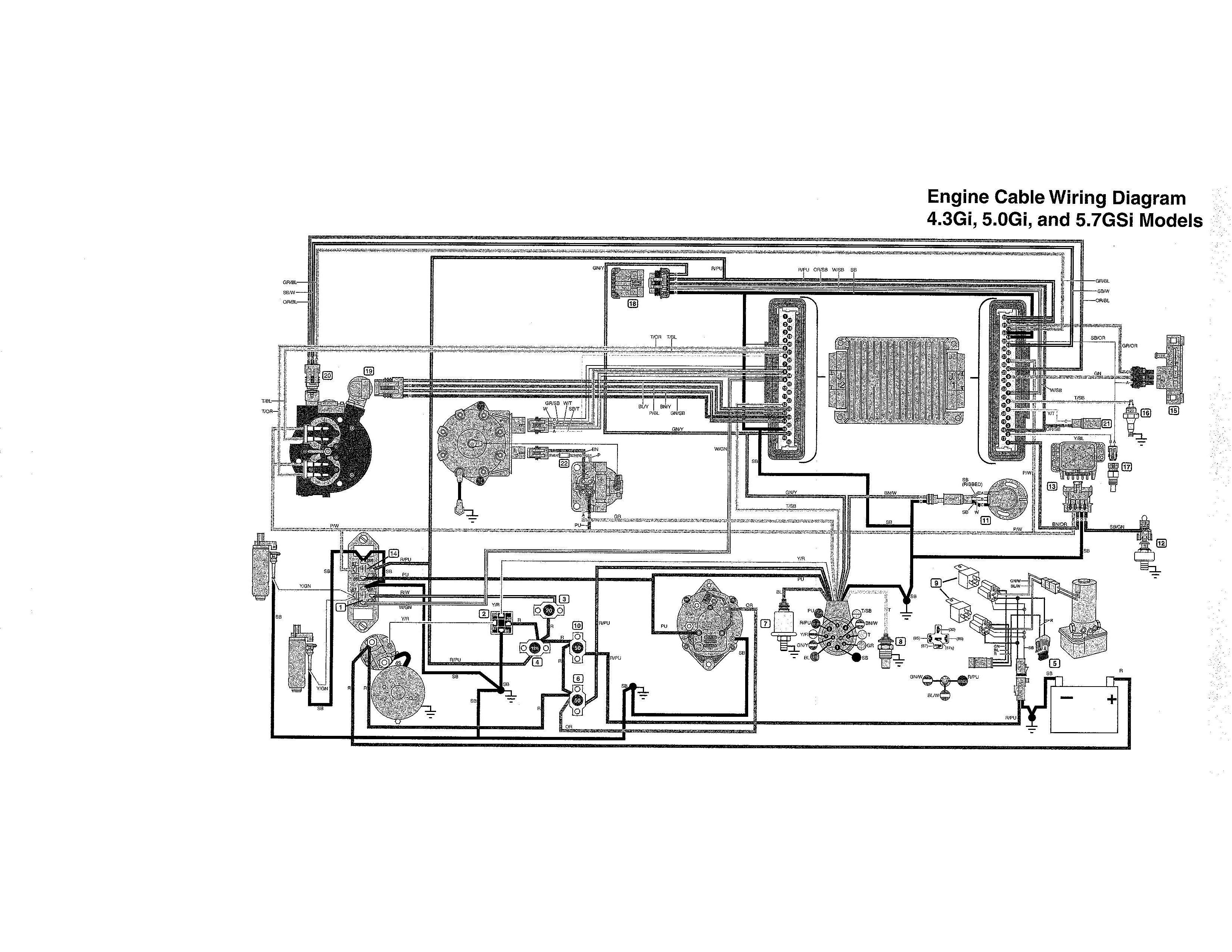
Electrical System Wiring Diagrams. Suppliment to Gi and GSi Models.
. 3 Tachometer Amplifier*.
4 Relays, Trim .. Volvo Penta of the Americas, Inc. Tacho sensor seems to be an inductive one and operates off the Tachometer( VDO) Problems on Volvo Penta Yep.
did indeed and getting same reading which would indicate that the wiring is fine. , #5. I could get a wiring diagram should you request it, but the tach wire hooks to the output I have a volvo penta in a striper, new.
The grey wire is not hooked up. The wiring diagram in the Volvo shop manual shows a tach amplifier and that the wire goes to the neg side of coil.
Any input on .Apr 17, · Tachometer(VDO) Problems on Volvo Penta Also does anyone have an idea how to check if the problem lies with the Tacho sensor or the head. Tacho sensor seems to be an inductive one and operates off the fuel pump drive gear.
Volvo penta GXi-E Pdf User Manuals. View online or download Volvo penta GXi-E Owner’s Manual.
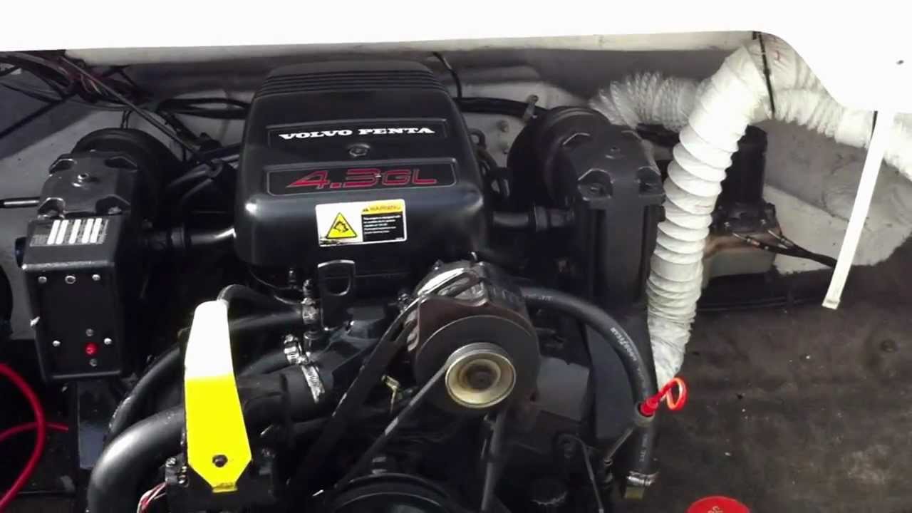
Volvo Volvo Penta GL: I have a Volvo Penta gl from I have a Volvo Penta gl from installed in my Four Winns Boat. Recently i have noticed that my battery is charging very poorly.
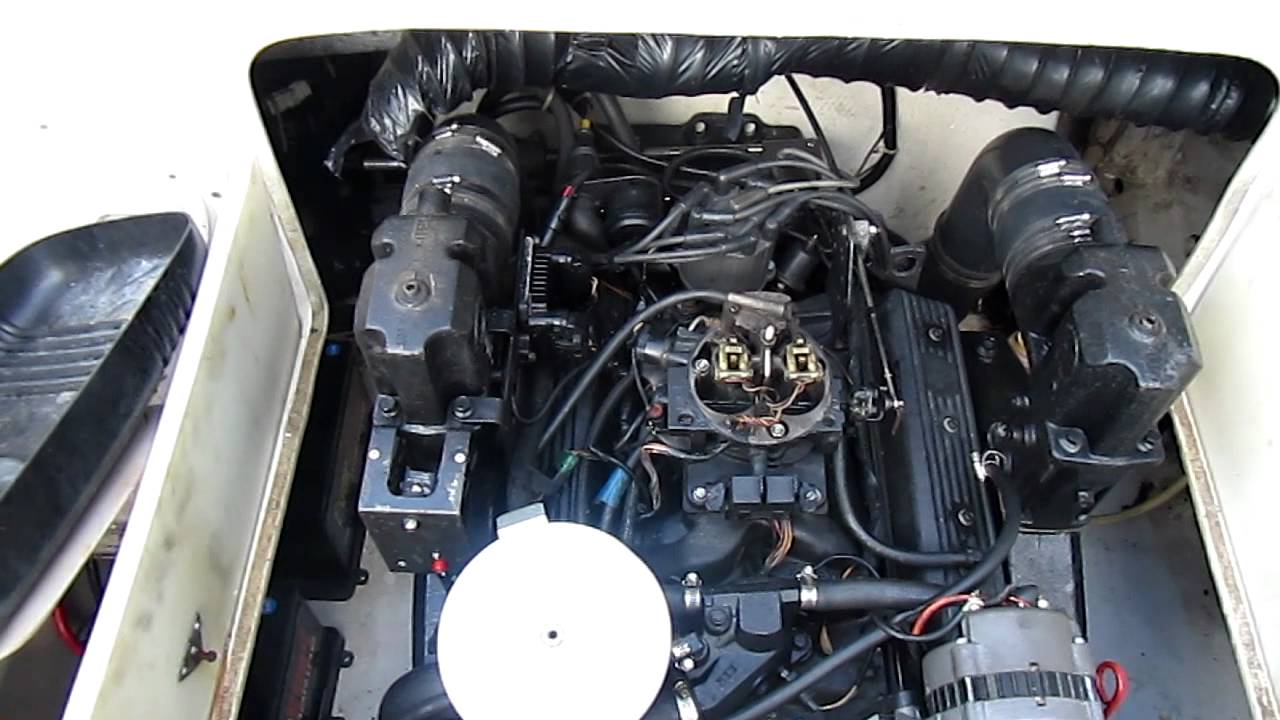
Jun 10, · Volvo Volvo Penta GL: I have a Volvo Penta gl from I have a Volvo Penta gl from installed in my Four Winns Boat. Recently i have noticed that 5/5.
Volvo Penta Gi-E Wiring Diagram for engine and Instrument Panel: 4: Volvo Penta Gi Cable Wiring Diagram: 2: Volvo Penta wiring diagram GSI: 4: Volvo Wiring Diagram Add On: 9: Wiring Volvo Penta diesel panel need help! 3: volvo penta aq alternator wiring diagram: 3: volvo penta starter and altinator wiring diagram.Google Webmaster Tools – Sitemap Notification ReceivedVolvo Penta Engines – Marine Parts Express
