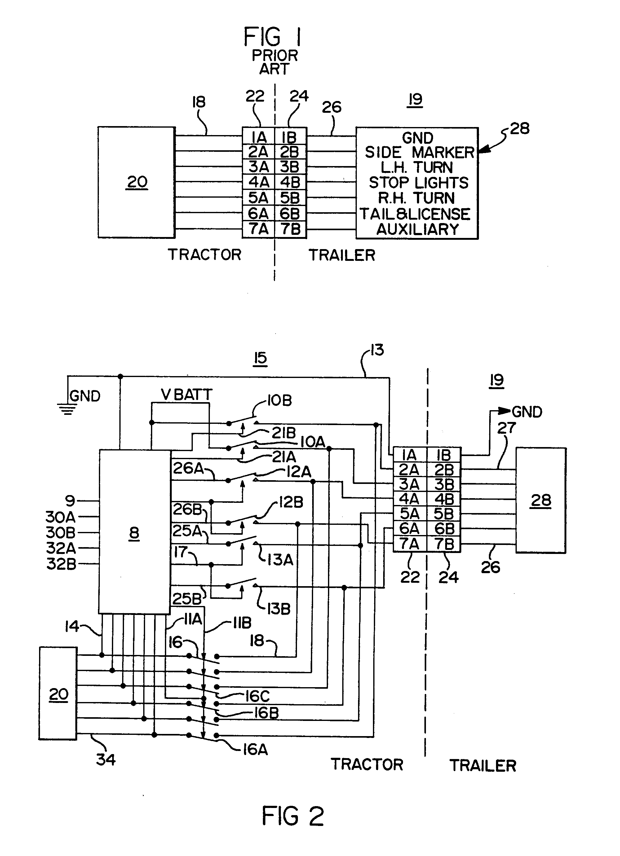
wheel speed sensor YE 1 wheel speed sensor BU 1 wheel speed sensor BU 2. Pinning – ISO mm² Pin 4 (GND).
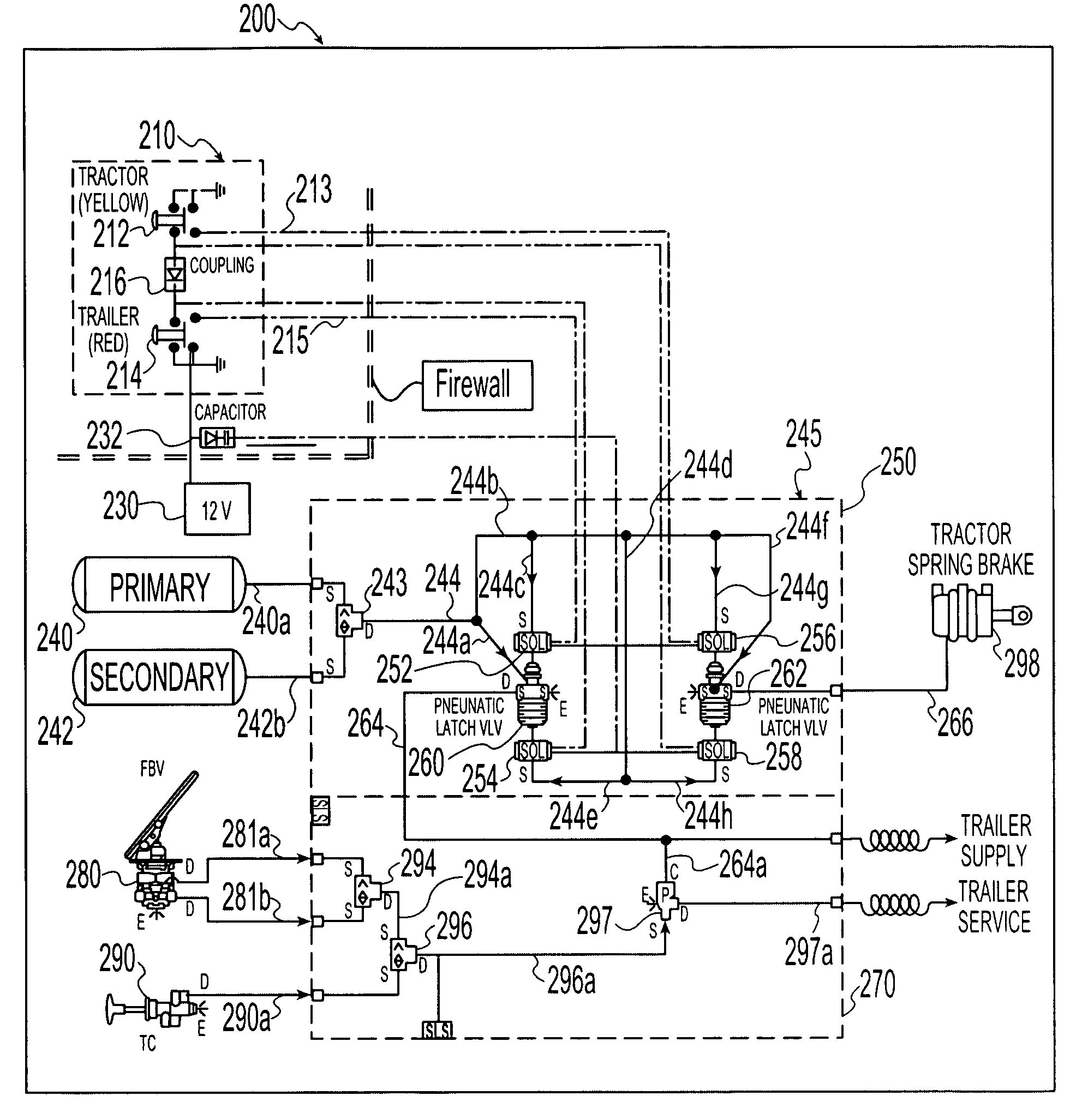
mm² Pin 1 (GND). Warning. Lamp.
Trailer ABS. Trailer ABS Components ABS relay modulator Electronic Control Unit (ECU)
ECU Wiring Diagrams · ABS Diagnostic Tools STEP 4: Blink Codes for Wabco VCS II version ECU. Use the table to Internal modulator failure, inlet valve #2.
Components. 2.
Edition. This publication is not subject to any update service. You will find the new .
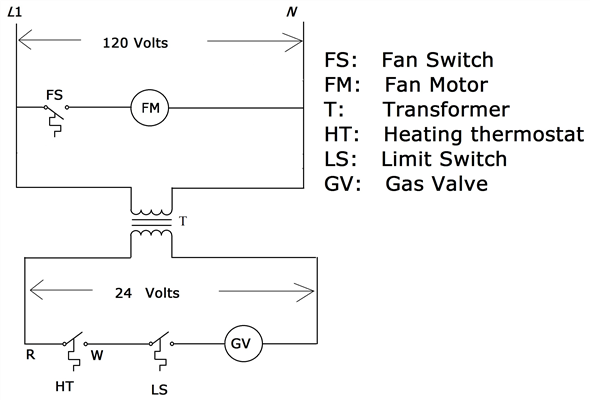
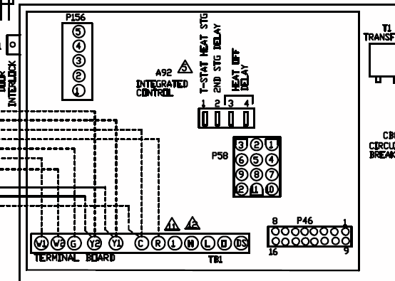
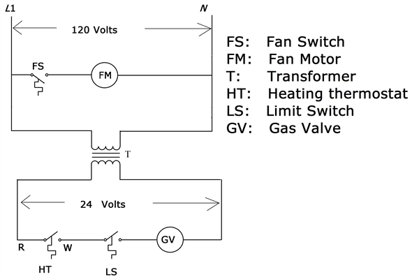
Wiring Diagram . VCS is a ready-to-install ABS system.
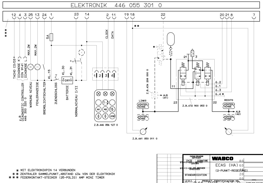
Fig. Wabco VCS II system ECU.
schematron.org-Wabco-EBS-tengelymodulátor-felújítás-4801050060
File size. File.
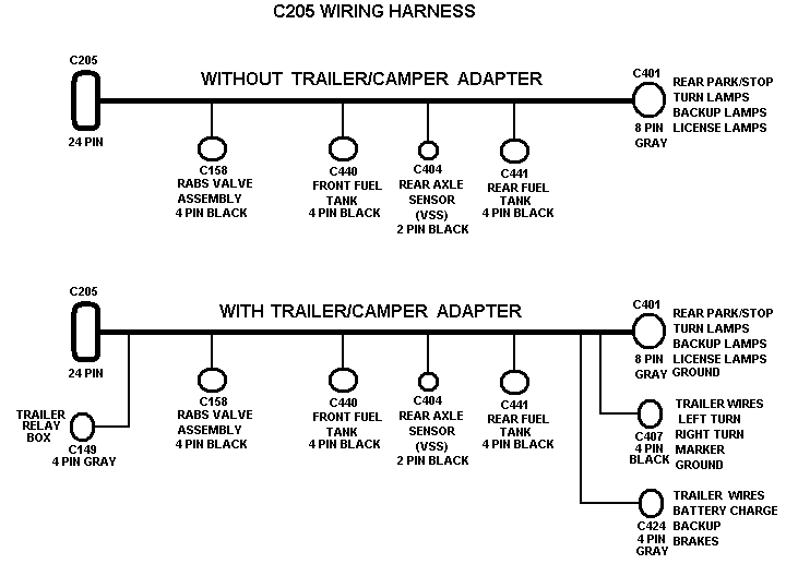
VCS II system ECU wiring diagram . Kb.
Download. Fig.
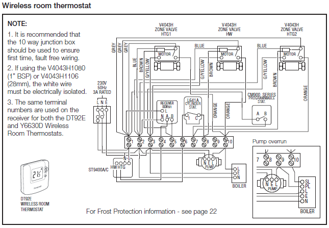
Haldex ABS MGX ECU (also apply to MGX 2 / MGX 2E. ECU Wiring Diagrams · ABS Diagnostic Tools STEP 4: Blink Codes for Wabco VCS II version ECU.
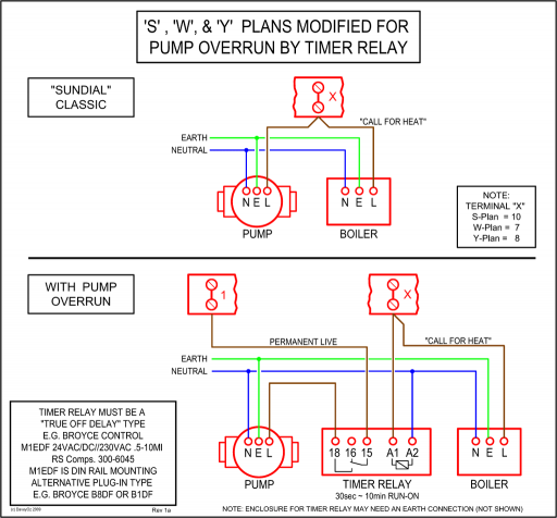
Use the table to Internal modulator failure, inlet valve #2.Fukuoka | Japan Fukuoka | Japan. ABS Troubleshooting for Trucks, Trailers, and Buses. STEP 3: Blink code identification and system response.
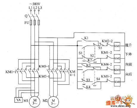
If you are unsure how to read ABS Blink Codes from the ECU, start by familiarising yourself with diagram below, and then, where appropriate, follow the step by step procedure in the table. ABS Troubleshooting for Trucks, Trailers, and Buses.
ECU Wiring Diagrams listed by Make and Model. Locate the correct wiring diagram for the ECU and system your vehicle is operating from the information in the tables below. INFORM::Index::Product number::Publications::Vehicles::Comparing Technical Sheets::Cross Reference: WABCO: Product Catalog: Index: Please select an index from.Wabco VCS II version ECU Blink Code ListWabco VCS version ECU Blink Code Lamp
