Start with a closed-loop setup utilizing vertical boreholes if space is limited. This configuration stabilizes inlet fluid temperature and ensures consistent performance year-round. Opt for high-density polyethylene piping for its longevity and resistance to underground pressure variations.
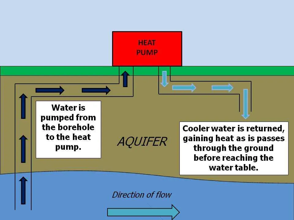
Ensure flow direction is clearly marked in all schematics. Fluid should circulate from the ground interface to the thermal exchange unit before returning. Incorporate flow meters and pressure gauges on both supply and return lines to monitor system behavior in real time.
Use a coaxial or plate-type exchanger within the interior unit to transfer energy between the loop fluid and the building’s internal medium. Plate exchangers offer compact design and high efficiency, especially in retrofitted installations with limited space.
Include a purge port and air separator to eliminate trapped gas and maintain optimal circulation. Always specify the antifreeze concentration suitable for the local climate to prevent freezing during low ambient conditions.
Control circuitry should integrate temperature sensors at inlet, outlet, and return points. This enables precise modulation of compressor activity, enhancing overall system responsiveness and reducing unnecessary energy draw.
Component Layout and Flow Strategy

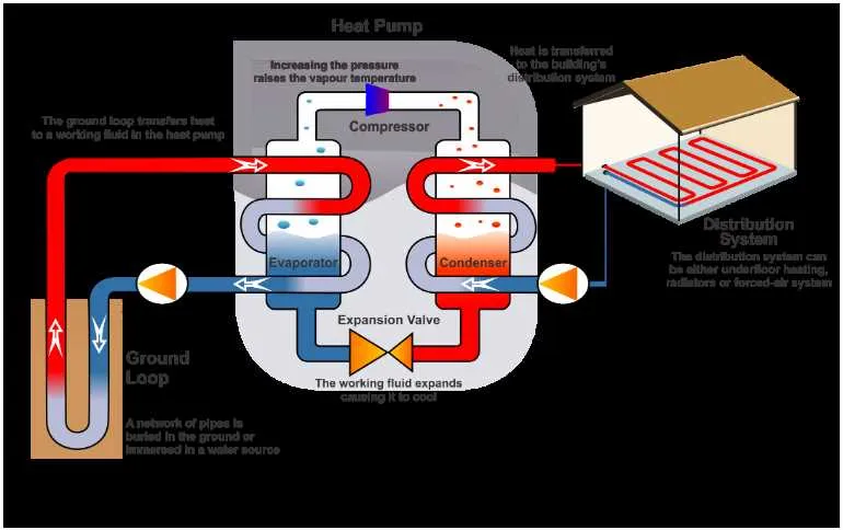
Begin by positioning the thermal exchange unit adjacent to the closed-loop system to minimize piping distance and reduce energy loss. Use insulated PEX or copper tubing for connections to prevent temperature degradation. The circulation route must ensure fluid enters the evaporator coil first, followed by the compressor, then the condenser, and finally the expansion valve before reentering the loop.
Install a reversing valve if seasonal operation is required, enabling directional change for climate control. The control board should be centrally mounted with direct links to the temperature sensors, fan relay, and flow switch. Avoid sharp 90-degree bends in piping; opt for gradual curves to maintain consistent pressure and avoid cavitation.
Ensure the fluid reservoir includes a temperature gauge and a check valve to prevent backflow. Position the fan coil unit near the conditioned space with accessible filters and dampers. Implement pressure sensors before and after the compressor for diagnostics and optimal performance tracking.
How to Interpret Component Symbols in Water Source Heat Pump Schematics

Start by identifying the compressor symbol, typically represented as a circle with an internal triangle or diagonal line. It connects directly to the condenser and is central to understanding refrigerant flow direction.
Locate the reversing valve using a four-way switch symbol, which usually has four ports and a slanted internal path indicating flow shift. This component determines the system’s operation mode.
Recognize fan motors by the capital “M” within a circle or square, often linked to air-handling units. Pay attention to control lines–solid for power, dashed for signal.
Thermostatic expansion valves are marked as angled lines intersecting with a bulb or diaphragm icon. Their placement affects subcooling and efficiency control across modes.
Electronic controllers are depicted as rectangles with internal abbreviations like “PCB” or “CTRL.” Wiring from sensors and relays leads into these, showing feedback mechanisms and logic control paths.
Symbols for temperature and pressure sensors appear as small circles labeled “T” or “P,” sometimes combined with arrows to indicate measurement direction. Their positions clarify safety and performance feedback loops.
Use manufacturer legend keys to decode proprietary notations. Symbols vary slightly across brands, especially for integrated control modules and variable-speed drivers.
Accuracy in symbol interpretation is essential for maintenance, diagnostics, and commissioning tasks. Always cross-reference with the legend and double-check wire IDs and terminal references.
Understanding the Flow Path of Refrigerant and Water in System Diagrams
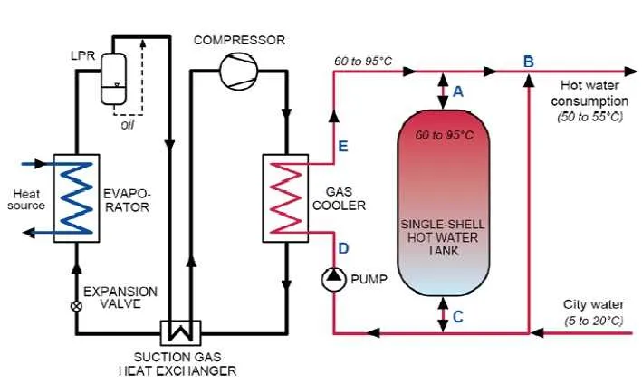
Begin by identifying the compressor, which initiates circulation by drawing low-pressure vapor and discharging it as high-pressure gas into the coil. Trace the line leading to the reversing valve; this component determines the flow direction, enabling either cooling or heating cycles.
From the valve, follow the path toward the coil submerged in the fluid loop. This exchanger allows energy transfer between the refrigerant and the circulating liquid. The refrigerant exits as a low-temperature, high-pressure fluid, which then flows to the expansion valve. This metering device drops the pressure, enabling the refrigerant to evaporate within the air-side coil.
Ensure the liquid circuit includes a flow controller, such as a motorized valve or variable-speed circulator, to regulate velocity through the exchanger. Monitor sensors placed before and after the coil for precise inlet and outlet temperature data. Check that flow arrows on the schematic confirm the correct sequence from condenser to evaporator.
Validate the schematic includes check valves and bypass routes, especially in multi-zone layouts. These elements prevent reverse circulation and allow partial-loop operation when full capacity is unnecessary. Use color-coded lines or directional symbols to quickly distinguish gas and liquid phases within the refrigerant path and verify pressure zones align with equipment ratings.
Wiring Layout and Control Circuit Connections in Water Source Heat Pump Diagrams
Ensure all power inputs are routed through a dedicated disconnect switch rated for the system’s voltage and current to provide safe maintenance isolation.
- Compressor Wiring: Use appropriately sized conductors following NEC guidelines to handle starting and running currents. Include overload protection devices inline.
- Fan Motor Connections: Connect the blower motor via a contactor controlled by the thermostat relay, ensuring the control voltage matches the motor specifications.
- Thermostat and Sensors: Wire temperature sensors and thermostatic controls to the control board using shielded cables to minimize electromagnetic interference.
- Control Board: Provide clear terminal identification for inputs such as compressor start, fan activation, and safety switches for straightforward troubleshooting.
- Safety Devices: Integrate high-pressure and low-pressure switches in series with the compressor control line to automatically shut off operation during fault conditions.
- Grounding: Establish a dedicated grounding conductor throughout the wiring harness, connected to all metallic components and enclosures per local electrical codes.
Follow a logical sequence for control circuit wiring:
- Power supply enters the control panel and feeds the main relay.
- Thermostatic demand energizes the compressor contactor coil.
- Simultaneously, the fan relay receives a signal to start the blower.
- Safety switches continuously monitor system parameters, breaking the circuit if unsafe conditions arise.
- Auxiliary outputs such as defrost heaters or circulation pumps are activated based on control logic.
Label all conductors and connectors clearly with durable markers to facilitate installation and future servicing. Verify continuity and proper control logic operation with a multimeter before powering the full assembly.