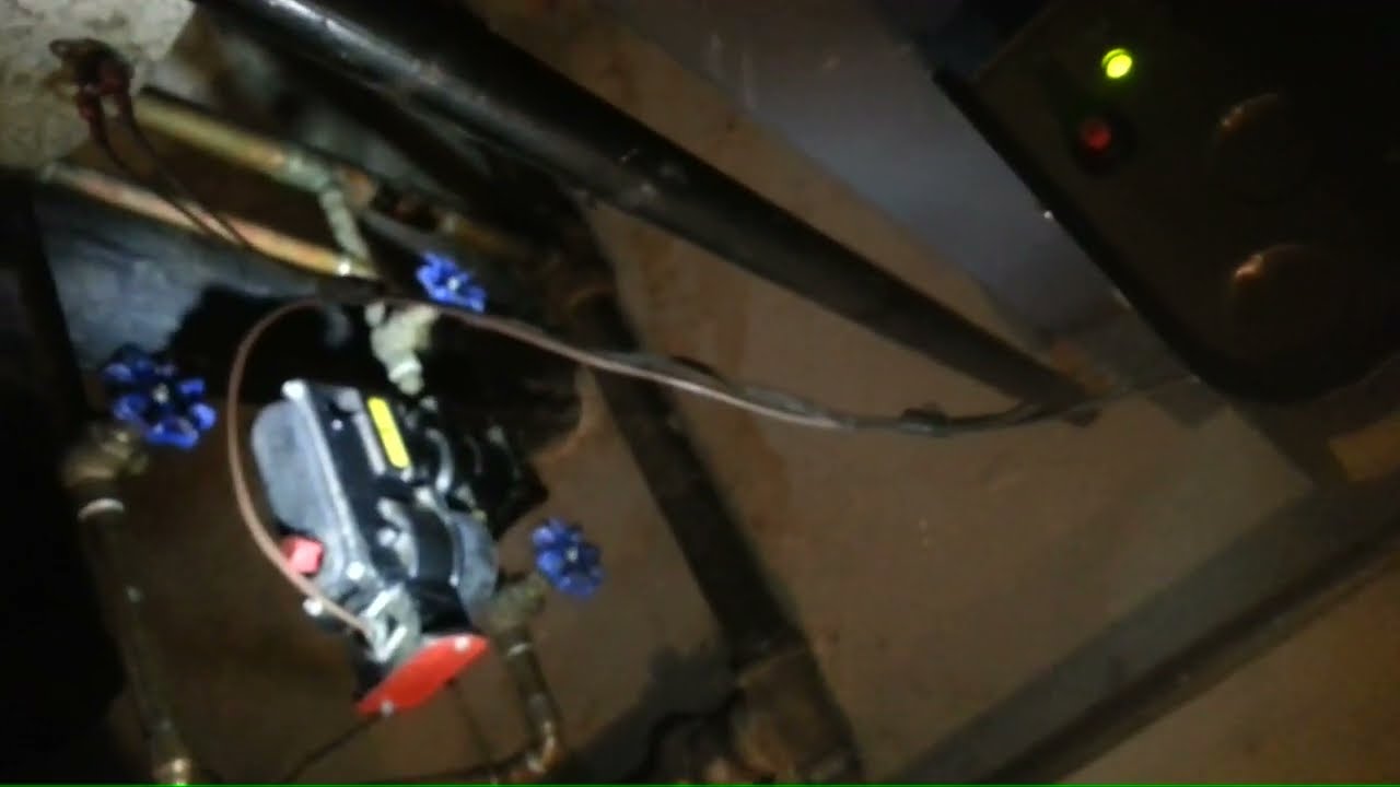
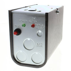
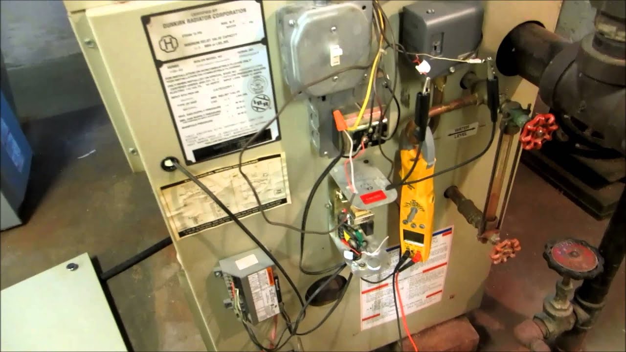
I am in the process of replacing the LWCO and WFE feeder. I have been following wire Diagram 4 on the WFE install manual.
Terminals 1 and 2 are the switch to shut off the boiler on low water. Once the water drops.
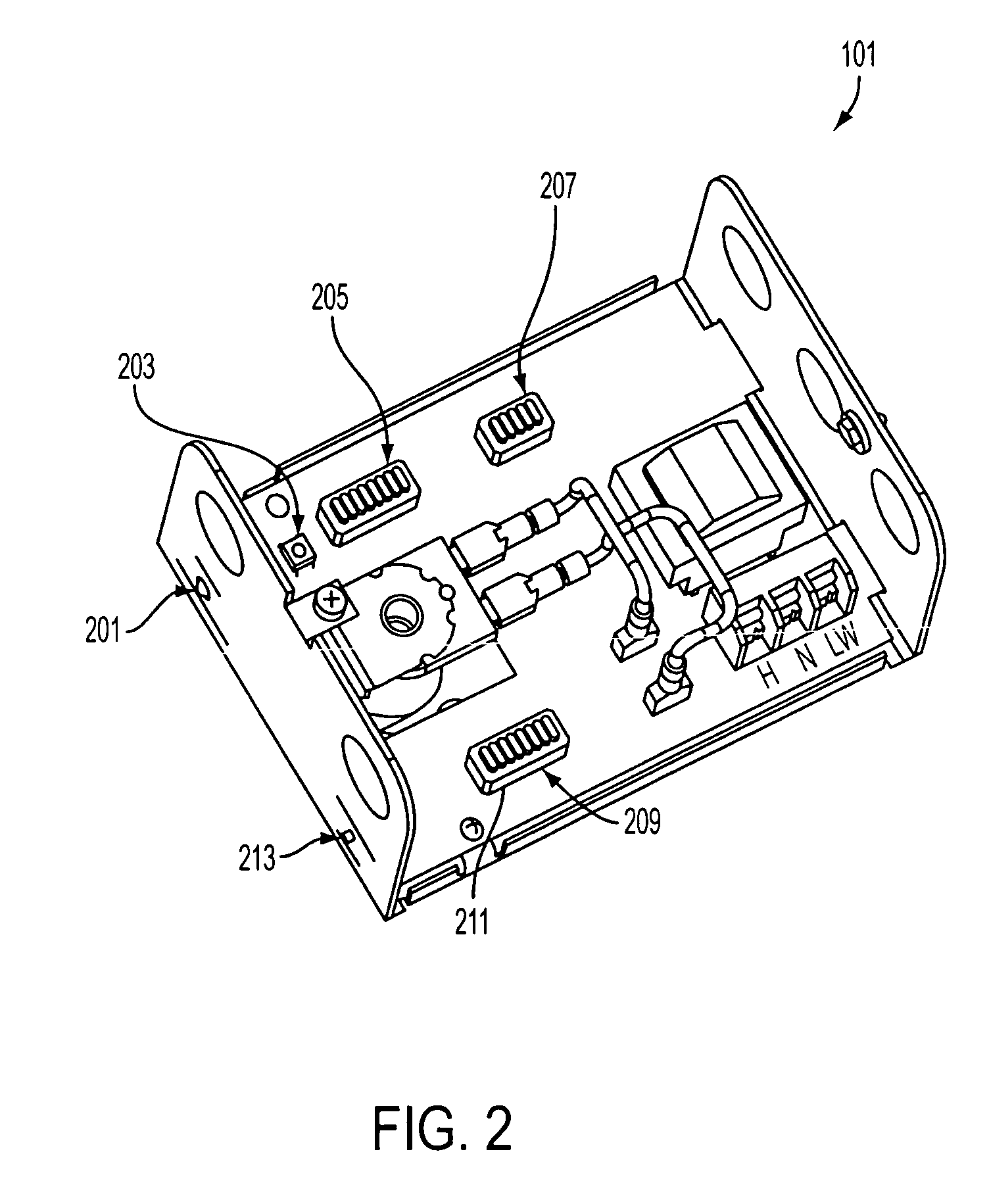
I am in the process of replacing the LWCO and WFE feeder. I have been following wire Diagram 4 on the WFE install manual.
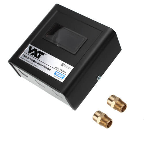
Terminals 1 and 2 are the switch to shut off the boiler on low water. Once the water drops.
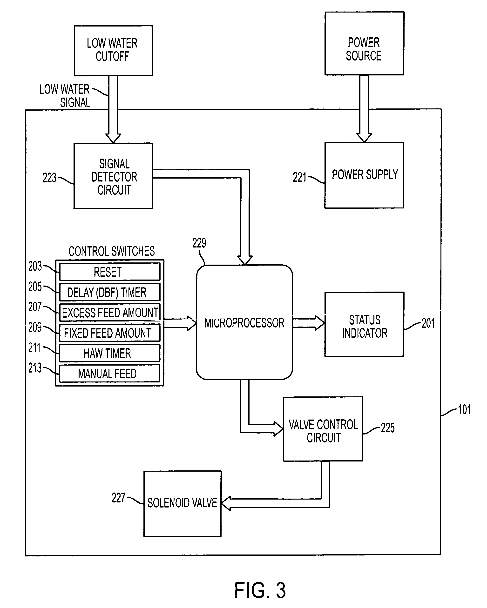
Feeder must be installed with a manual by-pass. Note: Arrow on VXT valve indicates direction of water flow.
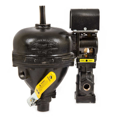
Step 3 Wiring Select the wiring diagram through. For all cycles on the WFE, the feeder will stop feeding when the selected McDonnell & Miller Universal Water Feeders are ideal for 24v and v models. NOTE: MV models are rated at 24 VA @ 24 VAC to VAC feeder. Wiring Diagrams: Series 69 Low Water Cutoff with M&M Model A Electronic Water.SKU: MH 3 in stock; Ships within 10 business days; McDonnell & Miller model number WFE is a Uni-Match 24 volt electric water feeder with manual feed .
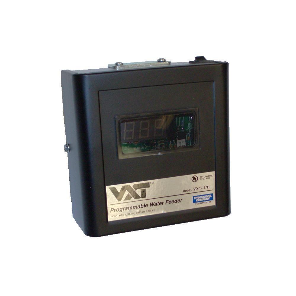
mcdonnell miller 67 wiring diagram – What’s Wiring Diagram? A wiring diagram is a kind of schematic which utilizes abstract pictorial icons to show all the affiliations of elements in a system.
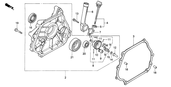
Nov 27, · Hi guys, how hard is it to install McDonnell and Miller Unimatch volt WFU water feeder? I have a Series A McDonnell and Miller water feeder installed already, and want to .
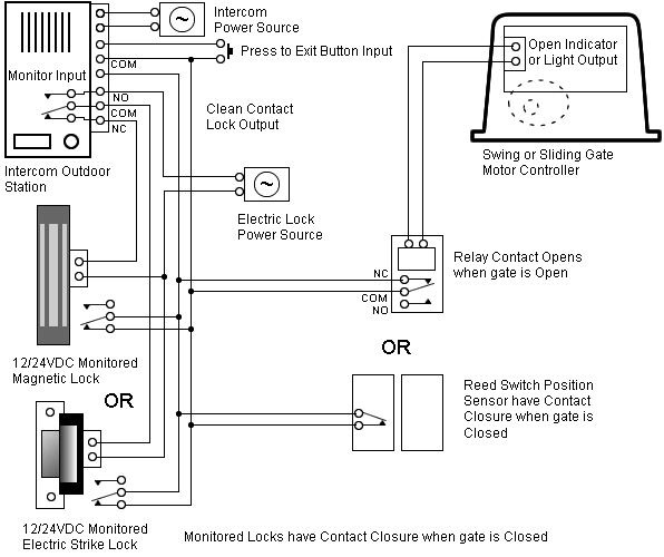
Water Feeder Wiring Diagram – Another Blog About Wiring Diagram • step 3 wiring mcdonnell miller ps series hydrolevel vxt 24 rh manualsdir com wfe water feeder wiring diagram vxt water feeder wiring diagram. Electric Water Feeder • Before using this product, read and understand instructions.
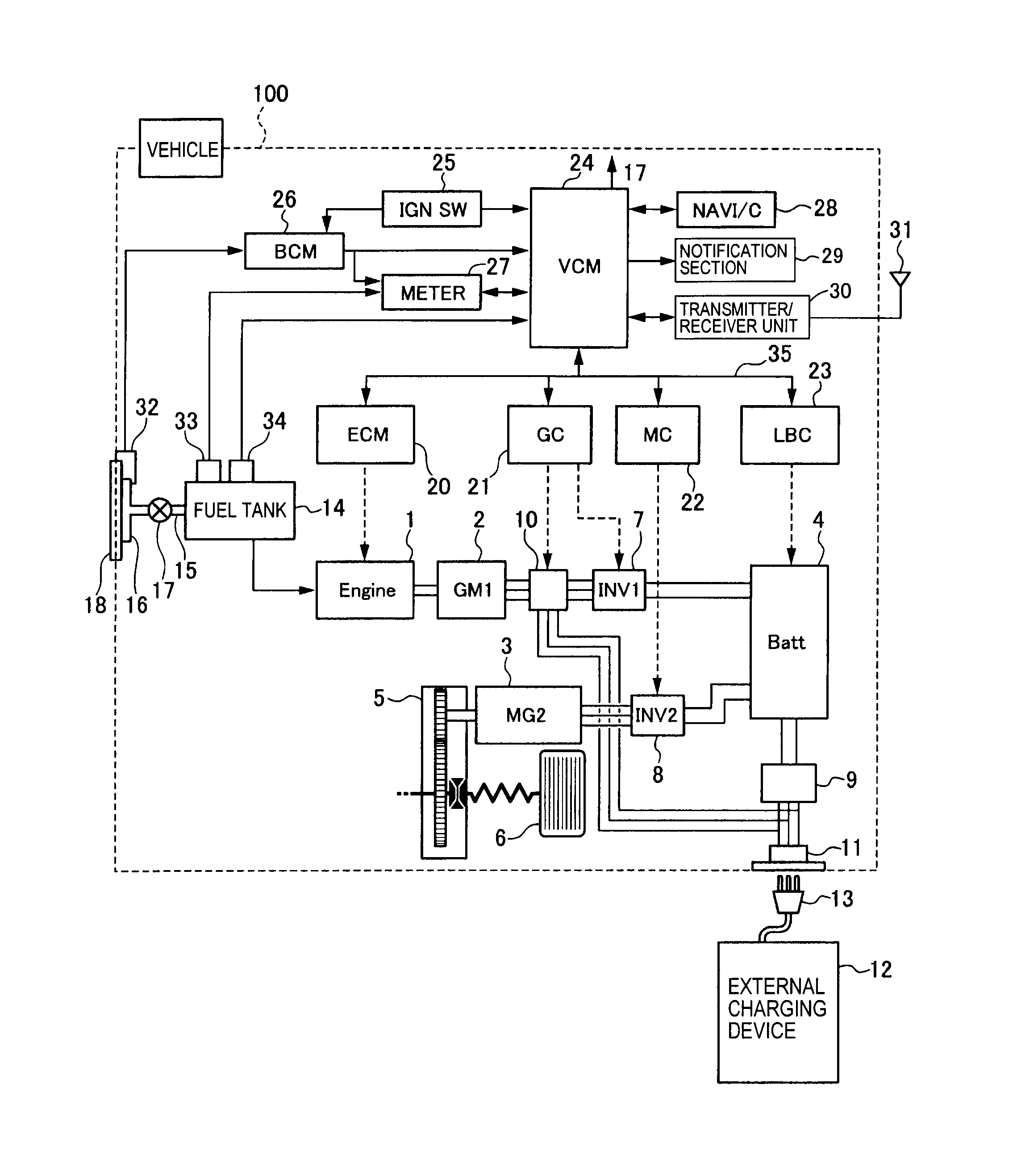
•Save these instructions for future reference. Wiring Diagram Legends 1.
Bold lines indicate action to be taken in Step shown. 2. Grey lines indicate existing wiring.WARNING.

Before using this product, read and understand instructions. – PDFWater Feeder Wiring Diagram | Wiring Library
