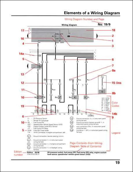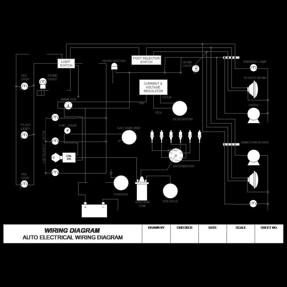
To accurately interpret electrical connections in vehicles, focus on the standard notations that represent components and their links. Each element, from power sources to sensors, has a designated mark, ensuring clarity in identifying their roles within the system. Familiarity with these indicators is essential for anyone involved in maintenance or repair work.
Fuse and Relay markers are crucial for understanding the protective mechanisms in any vehicle’s electrical system. These markers will often include a rectangle with a specific internal numbering or a double line, each variation representing the capacity or function. Recognizing these variations can help prevent misinterpretation when troubleshooting power issues.
Power and Ground symbols follow a standardized form, typically indicated by a bold line for positive connections and a dashed line for grounding. Knowing these distinctions is key when diagnosing faulty circuits or when trying to install additional electrical devices. The consistency of this notation reduces error in real-time repairs.
When working with circuit layouts, it’s also important to recognize different types of connections. For example, junctions where wires meet are represented by a simple node, often accompanied by a number. Each number corresponds to a specific connection type, helping you trace and troubleshoot the flow of electricity with ease.
Electrical Circuit Representation in Vehicles
For effective vehicle electrical system troubleshooting, understanding the schematic representation of components is essential. Here are key tips to interpret these complex connections:
- Grounding: Ground connections are usually shown with a downward-facing triangle symbol. Ensure that these points are properly linked to avoid short circuits.
- Power Supply: Positive terminals or power sources are commonly represented by a plus sign (+) or a line with a circle, indicating current flow direction.
- Switches: Toggle switches are illustrated by a simple open or closed break in the line. Different types of switches are shown with various angles to indicate their position.
- Connectors: These are depicted with a circle containing multiple lines emerging outward. Their positioning indicates where components can be linked or disconnected.
- Fuses: A fuse is typically marked by a rectangle or a line that breaks with an X through it. Always verify the correct rating when replacing to avoid electrical hazards.
Recognizing these elements simplifies the repair or modification process. Pay close attention to the scale of connections and orientation of symbols for accurate interpretation.
For efficient diagnostics, always cross-check the color codes and numbering used alongside the visual representations. Color coding assists in quickly identifying circuit types and their respective voltages.
Understanding the Basic Icons for Automotive Circuits
When interpreting technical drawings for electrical systems, focus on mastering the key representations. The primary shapes and lines indicate specific components and connections, providing a clear view of how electrical elements interact. For instance, a circle typically represents a switch, while a rectangle may indicate a power source. A line connecting two points often means a direct connection between components, and if the line has a dot, it signifies a junction.
Resistors are often shown as a zigzag line. Capacitors are represented by parallel lines with a gap between them. In contrast, diodes are symbolized by a triangle pointing toward a line. These representations allow for easy identification of parts without needing text descriptions, making it essential to learn them for efficient troubleshooting.
Additionally, ground connections are often depicted by a set of three horizontal lines stacked, decreasing in length from top to bottom. The battery is usually drawn as two parallel lines, with one longer than the other, to indicate the positive and negative terminals.
Be mindful that these icons may slightly vary depending on the region or manufacturer, but mastering the standard shapes will give you a solid foundation in understanding any schematic layout.
How to Read and Interpret Electrical Circuit Symbols in Car Schematics
Start by identifying the basic components, such as switches, fuses, relays, and sensors. Each element is represented by a specific shape, which corresponds to its function. For instance, a rectangle typically represents a fuse, while a circle is often used for a bulb or light. Recognizing these basic shapes will allow you to navigate through the schematic more efficiently.
Connections between components are shown as lines, with different line styles indicating various types of connections. Solid lines usually represent direct electrical paths, while dashed lines can indicate control or signal paths. Pay attention to the direction of the current flow, marked by arrows, to ensure you understand the path of electricity.
For components with multiple terminals, such as motors or actuators, focus on the labels next to the shapes. These labels often indicate the terminal numbers or functions, helping you trace how power is distributed through the system. If a component has a ground connection, it will typically be marked with a symbol representing earth or negative polarity.
Power sources are usually marked with a + or – sign, indicating the positive or negative sides of the circuit. Make sure to check the voltage ratings and ensure they align with the specifications of the components to avoid damage.
Lastly, familiarize yourself with specialized symbols that may appear in advanced circuits, such as relays or controllers. These often include additional notations or circuit pathways, which might be less intuitive at first glance. Take time to learn these in detail for better understanding of complex electrical systems.
Common Mistakes and How to Avoid Them

One of the most frequent errors is neglecting proper color coding. Always double-check the wire colors before making connections. Misidentifying the wire can lead to system malfunctions or short circuits.
Another common issue is incorrect pin placement. Ensure you follow the exact order and alignment indicated in the documentation. Incorrect pin connections can cause electrical failures and may even damage components.
Don’t skip continuity testing. This simple step can prevent significant issues. Verify all connections are properly established and there are no open circuits or shorts before powering up the system.
Be mindful of the grounding process. A poor ground connection can create a range of electrical issues, from intermittent failures to complete system shutdowns.
Lastly, improper wire gauge selection is a serious problem. Using wires with inadequate thickness can cause overheating and increase resistance, leading to potential fire hazards. Always match the gauge with the specifications for the load it will carry.
| Common Error | How to Avoid |
|---|---|
| Misidentifying wire colors | Verify colors with the manual before connecting |
| Incorrect pin placement | Check the pinout carefully before making any connections |
| Skipping continuity tests | Perform continuity checks on all connections |
| Poor grounding | Ensure a solid and reliable ground connection |
| Using incorrect wire gauge | Choose wires that match the load requirements |