
A schematic diagram is a visual representation of an electrical circuit using simple symbols and lines to show the flow of electrical current. It is a blueprint that allows engineers, technicians, and hobbyists to understand how a circuit works and troubleshoot any issues that may arise.
In electronics, a schematic diagram is crucial for the design and analysis of circuits. It shows the various components used in a circuit, such as resistors, capacitors, and transistors, and how they are interconnected. By following the lines and symbols, one can determine the path of current and voltage throughout the circuit.
Schematic diagrams are essential for a variety of electronic applications, including the design and construction of printed circuit boards (PCBs), the repair and maintenance of electronic devices, and the development of new electronic systems. They provide a clear and concise representation of a circuit, allowing engineers to communicate their ideas and designs effectively.
What is a schematic diagram?
A schematic diagram is a graphical representation of an electrical circuit. It uses symbols to represent the different components of the circuit and shows how they are interconnected. Schematic diagrams are an essential tool for engineers and technicians in the field of electronics, as they provide a visual representation of the circuit’s structure and function.
Schematic diagrams are used in various industries, including electronics, telecommunications, and automotive. They are often used for designing and troubleshooting circuits, as well as for documentation and communication purposes. By following the symbols and connections shown in a schematic diagram, engineers and technicians can better understand how a circuit works and identify any potential issues or faults.
Typically, a schematic diagram will include various symbols representing components such as resistors, capacitors, transistors, and integrated circuits. Lines are used to indicate the electrical connections between these components. Additionally, the diagram may include labels and annotations to provide further information about the circuit, such as voltage values or component values.
Overall, schematic diagrams play a crucial role in the field of electronics as they allow engineers and technicians to visualize and analyze complex electrical circuits. They are an indispensable tool for designing, troubleshooting, and documenting circuits, and are widely used in industries where electrical systems and circuits are involved.
Definition and purpose of a schematic diagram
In electronics, a schematic diagram is a visual representation of a circuit using symbols and lines to show the connections and components involved. It is a simplified and standardized way of illustrating the structure and function of an electrical or electronic system.
The main purpose of a schematic diagram is to provide a clear and concise overview of how the various components and connections are arranged in a circuit. It allows engineers, technicians, and electricians to quickly understand and analyze the circuit design, troubleshoot problems, and make modifications if necessary.
A schematic diagram typically includes symbols that represent different electronic components such as resistors, capacitors, transistors, and integrated circuits. These symbols are interconnected by lines that indicate the flow of current. The diagram also usually includes labels and annotations to provide additional information about the circuit.
Schematic diagrams are essential tools in electronics because they allow for effective communication and documentation of circuit designs. They are used in various fields, including electrical engineering, computer science, and telecommunications. Whether designing a new circuit, repairing an existing one, or teaching others about electronics, the schematic diagram is an indispensable resource.
Components of a schematic diagram
A schematic diagram is a graphical representation of an electronic circuit, showing the interconnections between various components. It is a vital tool in electronics design and troubleshooting. A well-drawn schematic diagram can convey crucial information about the components used, their connections, and the overall functionality of the circuit.
In a typical schematic diagram, there are several key components that are commonly found:
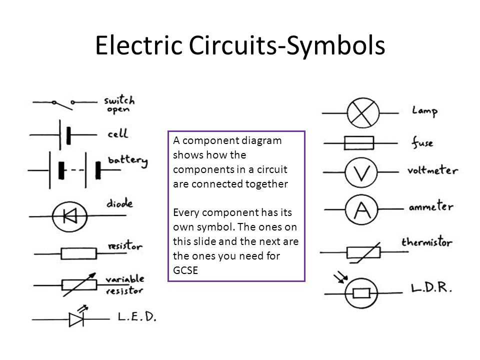
1. Symbols:
In order to represent various electronic components, symbols are used in a schematic diagram. These symbols are standardized and provide a concise way of representing components such as resistors, capacitors, transistors, and integrated circuits. Each component has its own unique symbol that helps identify its function and electrical properties.
2. Lines and Dots:
Lines and dots are used to represent the interconnections between components. The lines indicate physical connections, while dots indicate junctions or points of connection. These connections are essential for understanding how the various components are connected and how current flows through the circuit.
3. Labels and Values:
Labels and values are used to provide additional information about the components. Labels are used to identify individual components or groups of components, while values indicate the specific characteristics or ratings of the components, such as resistance values or capacitance values. These labels and values are important for proper understanding and analysis of the circuit.
4. Power Supply and Ground:
A schematic diagram typically includes symbols for the power supply and ground connections. These symbols indicate the source of electrical energy and the reference point for potential differences. The power supply and ground connections are important for determining the overall voltage and current flow within the circuit.
- Symbols represent various electronic components
- Lines and dots represent interconnections
- Labels and values provide additional information
- Power supply and ground symbols indicate the energy source and reference point
In conclusion, a schematic diagram consists of various components such as symbols, lines, dots, labels, values, and power supply/ground symbols. These components work together to provide a clear and comprehensive representation of an electronic circuit, allowing engineers and technicians to understand and analyze its operation.
Understanding symbols and their representation

In electronics, schematic diagrams are used to represent the different components and connections in an electronic circuit. These diagrams use symbols to represent the various electronic components, such as resistors, capacitors, transistors, and integrated circuits. Understanding these symbols is essential for interpreting and designing electronic circuits.
The symbols used in schematic diagrams are standardized, meaning that they have specific meanings and representations. For example, a resistor is represented by a zigzag line, while a capacitor is represented by two parallel lines. Each symbol represents a specific electronic component and its function within the circuit.
It is important to familiarize yourself with these symbols and their representation in schematic diagrams. This can be achieved by referring to a schematic diagram symbol reference guide or by studying electronics textbooks or online resources. By understanding the symbols, you will be able to interpret and design electronic circuits more effectively.
In addition to individual component symbols, schematic diagrams also include symbols for connections and circuit elements, such as power supplies, ground, and signal paths. These symbols are used to represent how the different components are connected and interact with each other within the circuit.
In conclusion, understanding symbols and their representation is crucial in electronics. By familiarizing yourself with these symbols, you will be able to interpret and design electronic circuits more effectively. Whether you are studying electronics or working on electronic projects, mastering the symbols used in schematic diagrams is an essential skill.
Benefits of using schematic diagrams
When it comes to understanding and designing electronic circuits, schematic diagrams play a significant role. These diagrams allow engineers and technicians to visualize the layout and connections of various electronic components, making it easier to troubleshoot, repair, or modify the circuit. Here are some benefits of using schematic diagrams:
- Clarity and organization: Schematic diagrams provide a clear representation of the circuit layout, making it easier to identify each component and its role within the system. This helps to maintain organization and ensure that all connections are correctly labeled and documented, reducing the chances of errors during assembly or repair.
- Troubleshooting: When a circuit malfunctions, having a schematic diagram can be invaluable in locating the source of the problem. By visually following the signal flow and understanding how each component interacts with the others, technicians can quickly identify faulty components or connections and take the necessary steps to rectify the issue.
- Modifications and upgrades: Schematic diagrams provide a blueprint for the circuit, making it easier to make modifications or upgrades. Engineers can identify areas that need improvement or changes and determine the best course of action without the need for extensive reverse engineering. This enables faster and more efficient circuit modifications during the prototyping or production stage.
- Documentation and sharing: Schematic diagrams serve as an essential documentation tool, allowing engineers to record and communicate circuit designs. They can be shared with colleagues, manufacturers, or clients to ensure everyone involved understands the circuit’s structure and functionality. This helps to foster collaboration and enables smooth communication throughout the design and production process.
- Education and learning: Schematic diagrams are widely used in electronics education as a means to teach students about circuit design and operation. By analyzing and understanding these diagrams, students gain hands-on experience and develop essential skills in circuit analysis, troubleshooting, and design. Schematic diagrams provide a practical and visual representation that enhances the learning process.
In conclusion, schematic diagrams offer numerous benefits in the field of electronics. They provide clarity and organization, aid in troubleshooting, facilitate modifications and upgrades, serve as documentation and sharing tools, and enhance education and learning in circuit design. These advantages make schematic diagrams an indispensable tool for engineers, technicians, and students alike.
Enhancing troubleshooting and understanding
Using schematic diagrams in electronics can greatly enhance the troubleshooting process and improve overall understanding of how a circuit works. These diagrams provide a visual representation of the circuit, allowing technicians and engineers to easily identify components, connections, and values.
Identifying components: Schematic diagrams categorize different components in a circuit, such as resistors, capacitors, transistors, and integrated circuits. By referencing the diagram, technicians can quickly locate specific components and check their values or states.
Understanding connections: Schematic diagrams depict the connectivity of various components, including how they are connected with each other and with power sources. This helps technicians identify potential issues with faulty connections, short circuits, or open circuits.
Checking values: Schematic diagrams often provide information about the values of different components, such as resistance, capacitance, or voltage ratings. By comparing these values with actual measurements, technicians can quickly identify components that are out of specification and potentially causing problems in the circuit.
Tracing signal flow: Schematic diagrams also show the direction of signal flow in a circuit. This allows technicians to trace the path of a signal and identify points where it may be getting distorted, attenuated, or lost. Understanding the signal flow can help pinpoint the specific components or sections of the circuit that need further investigation or troubleshooting.
Overall, schematic diagrams serve as valuable tools in the field of electronics. They provide a clear visual representation of a circuit, allowing technicians and engineers to troubleshoot more efficiently and gain a deeper understanding of how the circuit functions.
How to Read a Schematic Diagram
In order to understand and interpret a schematic diagram in electronics, it is important to have a basic understanding of the symbols and conventions used in these diagrams. Schematic diagrams are graphical representations of circuits, showing how different components are interconnected and the flow of current in the circuit.
1. Identify the components: The first step in reading a schematic diagram is to identify the different components that are represented. These components can include resistors, capacitors, diodes, transistors, and other electronic devices. Each component is represented by a specific symbol, which may vary depending on the standards used.
2. Understand the connections: Once the components are identified, it is important to understand how they are connected to each other. The connections are represented by lines or wires in the schematic diagram. The lines indicate the flow of current, while the junctions represent the points where the different components are connected.
3. Follow the flow of current: In order to understand the circuit operation, it is important to follow the flow of current in the schematic diagram. This can be done by starting at the power source, such as a battery or power supply, and following the lines and connections to understand how the current flows through the different components.
4. Pay attention to labels and values: Schematic diagrams often include labels and values associated with the components. These labels can provide important information about the characteristics of the components, such as resistance values or capacitance values. It is important to pay attention to these labels in order to fully understand the circuit.
5. Refer to the component datasheets: In some cases, it may be necessary to refer to the datasheets of the components used in the circuit. The datasheets provide detailed information about the characteristics and specifications of the components, which can help in understanding their function in the circuit.
By following these steps and familiarizing yourself with the symbols and conventions used in schematic diagrams, you can effectively read and interpret these diagrams to understand the functioning of electronic circuits.
Step-by-step guide to interpreting a schematic diagram
In order to interpret a schematic diagram in electronics, follow these steps:
- Start by identifying the major components shown in the schematic. These may include resistors, capacitors, transistors, diodes, integrated circuits, and more.
- Examine the connections between the components. Look for lines or wires that connect the components together. These lines indicate the flow of electrical current.
- Pay attention to the symbols used for each component. Familiarize yourself with the various symbols used in electronics, as they represent different types of components and their functions.
- Analyze any labels or annotations on the schematic. These labels provide additional information about the components or the connections between them.
- Follow the flow of the circuit. Start at one point and trace the path of the current through the schematic. This will help you understand the overall functioning of the circuit.
- Identify any feedback loops or control mechanisms. These are typically represented by arrows or other markings on the schematic and are crucial for understanding how the circuit operates.
- Make note of any input or output connections. These are usually indicated with specific symbols and help you understand how the circuit interacts with external devices.
- Refer to any accompanying documentation or datasheets for further information about the components or the circuit design.
By following these steps, you will be able to interpret and understand a schematic diagram in electronics. Remember that practice is key, and the more you familiarize yourself with schematics, the easier it will become to analyze and interpret them.
Now that you have a better understanding of schematic diagrams, you can confidently delve into the world of electronics and use this valuable tool to design and troubleshoot circuits.