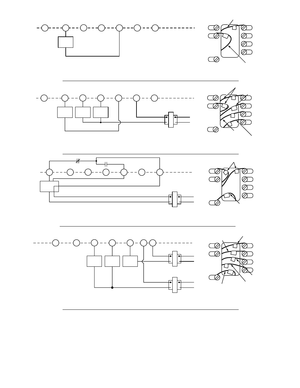
We include wiring diagrams and installation instructions for most zone valve model and . for a mixed-brand zone valve installation: Honeywell & White Rogers. TYPE HYDRONIC ZONE VALVES.

(2 WIRE). The contact arrangement of the switch is The schematic shows the valve in the closed position.

As the. Hi Scott, do you already have the zone valves wired up?
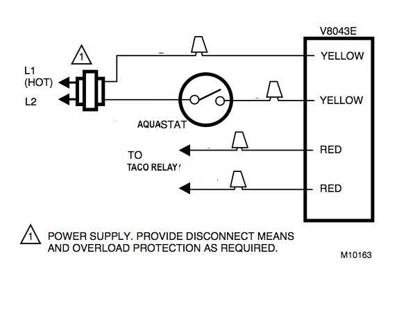
Where that diagram shows connections to T1 and T2 on the boiler control, you will I have deceided to replace the white rodgers valves since they are 30 years old. White Rodgers – 3/4″ Sweat Zone Valve (Three Wire) – 3/4″ Zone Valve Connections on valve are well marked and easy to attach wires either to.
schematron.org TECHNICAL HELP. RESIDENTIAL.

ZONE VALVES. TO AUXILIARY the valve fails to open check connections.
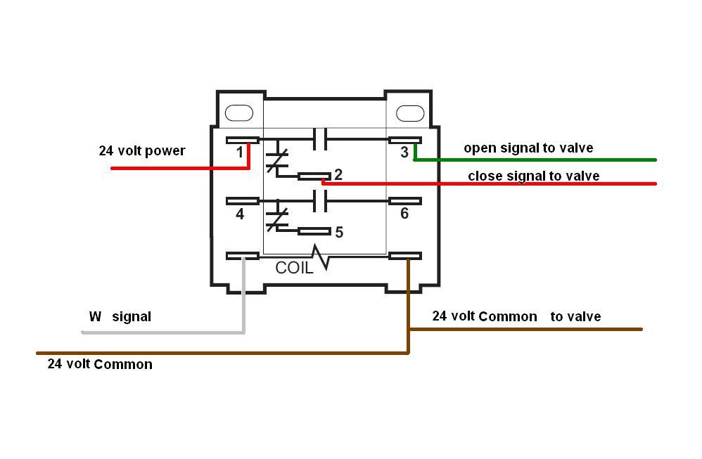
Replace motor.White Rodgers – 3/4″ Sweat Zone Valve (Three Wire) – 3/4″ Zone Valve (Three Wire) Features 15 PSI Maximum Differential Across Valve Degrees F Maximum Water Temperature 24 VAC 60Hz 50 PSI Maximum System Pressure. Jul 30, · It is a 3wire White Rodgers zone valve # There are three wires, red, white and green.
The old t’stat had red-to-red, white-to-white and the green wire attached to the Y terminal on a Honeywell series 20 t’stat. White Rodgers Zone Valve Wiring Diagram – If you have a White-Rodgers heat pump and thermostat system, or an Emerson thermostat, the wiring likely follows a particular pattern.
If you are installing a new thermostat, refer to the manufacturer’s instructions. They should contain a diagram of the wire terminals and indicate which wires go where.
valves. diagram for systems where burner and circulator operation is independent of thermostat additional zones fig. 6 using type zone valve diagram for systems where internal transformer of relay control supplies power for zone valves t2 t1-v1 v2-l1 z-l2 hot line n transformer must be n.e.c.
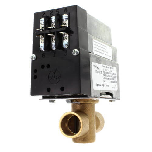
class 1 wiring circulator motor 1 2 3 to zone. The 30 year old zone valve that I have is marked: White Rodgers Zone A Flow Water valve Type 1in amp 25v ac The new and old valves look very similar but the new valve has 5 screw terminals marked 1 thru 5. The old valve has 5 wire inserts marked 1 thru 4.
I’ll try to send a diagram.Control a 3-wire zone valve with a 2-wire thermostat | Geek(Wisdom).comWhite Rodgers zone valve wiring – schematron.org Community Forums