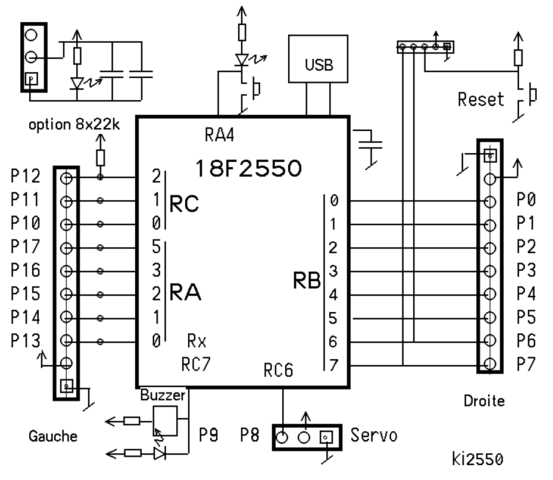
I’ll show you how to make a replacement for the standard remote that you can This Instructable is about making the control box for the fog machine.
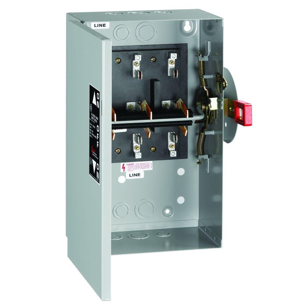
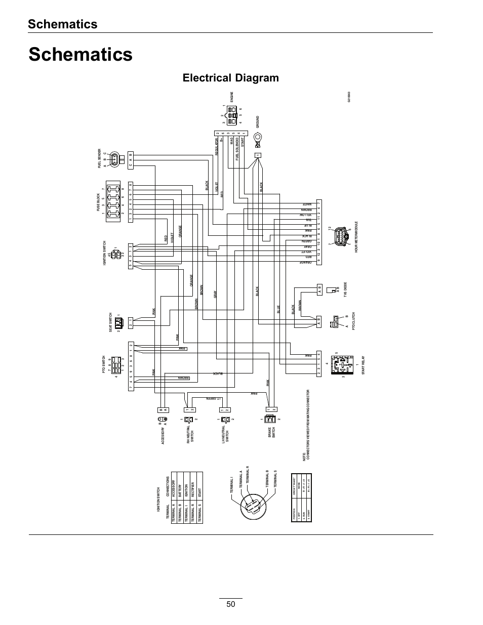
. and solder the wires onto the lugs, following the diagram (the solder lugs are on the left).
The remote uses two off the wires in the kettle lead (presumably + and guessing the components I have drawn up the (poor) diagram below. Hoists Direct Inc.
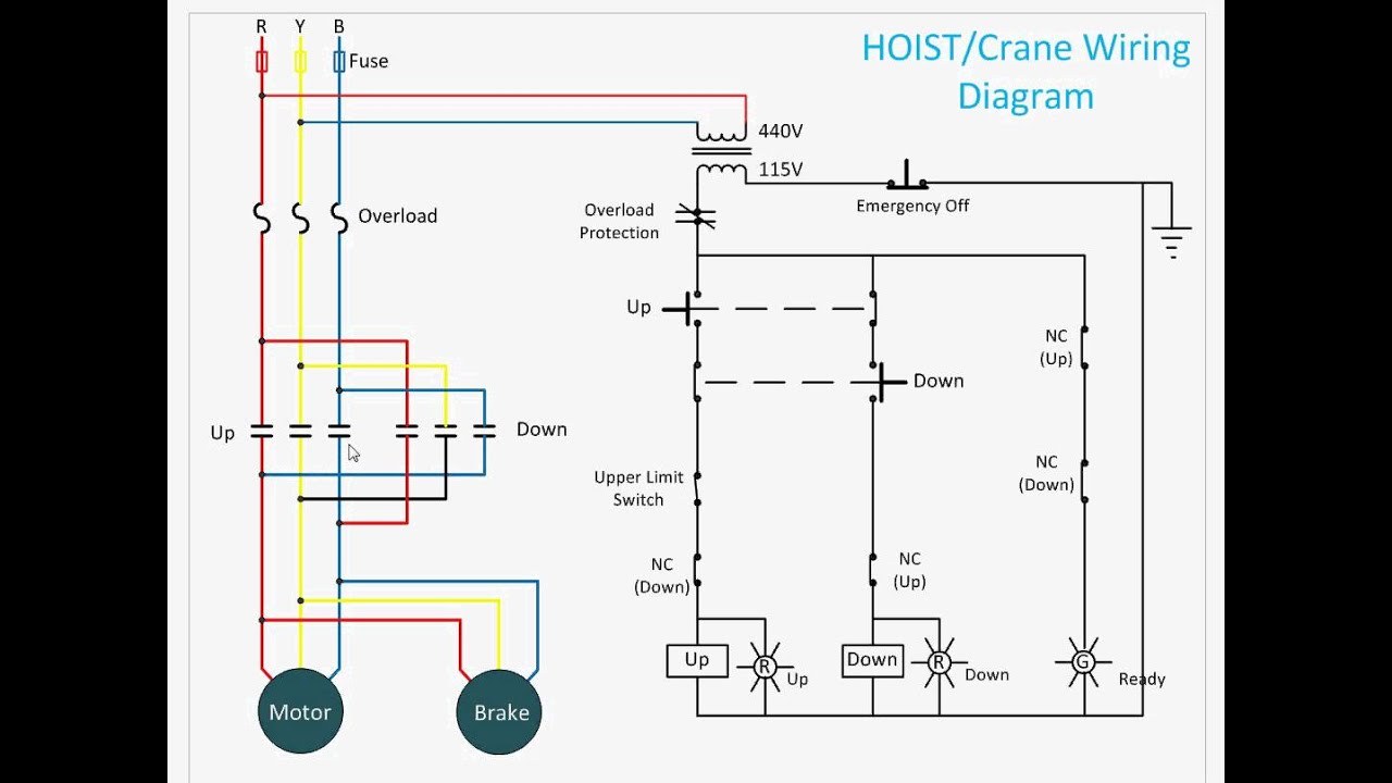
is a global distributor of high quality industrial hoist and crane hoisting equipment, fork lift components, wire rope hoists, 1-Ton and 2-Ton hoists , radio control systems, capstan hoists, cable hoists, electrification systems, Harrington 1-Ton Single Phase Electric Chain Hoist, 10′ of Lift, Hook Mounted. Hoists Direct offers radio control systems for operating hoists and cranes, manufactured by Hoists Direct offers many different radio control systems or RC systems for .
Enrange Flex EX 4-Button Radio System, 2-Motion, 2-Speed Coffing 1-Ton Single Phase Electric Chain Hoist, 10′ of Lift, Hook Mounted JLC Does anyone know how the Chauvet 5 pin timers are wired? I am wondering if I can reuse my timer on another machine if I decide not to However, I have not yet looked into which fogger remote pins in the din I am not a hardware expert and is the first schematic I made so hopefully this all makes sense.Hoists Manuals and Wiring Diagrams.
Hoists Direct is pleased to offer some of the most common manuals and technical information for FREE download. System Sensor warrants its enclosed product to be free from defects in materials and workmanship under normal use and service for a period of three years from date of manufacture.
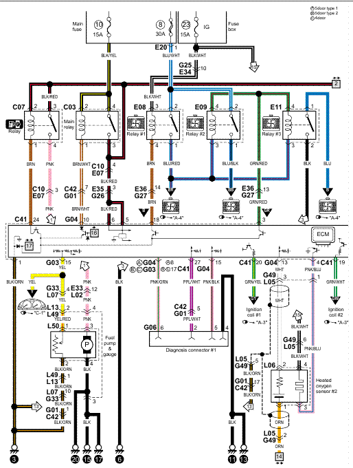
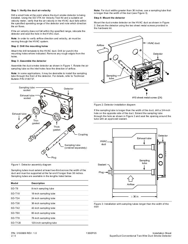
2. Electric wiring, see instruction B. 3.
Adjustment, see instruction C. 4.
Manual operation, see instruction D. NOTE: Only electric wiring, acc.
to instruction B, is required when the actuator is delivered from Remote Control mounted on a valve. It is adjusted and ready for operation.
WARNING! Remove power before the cover is dismantled!
the remote (Fig. 5A).
NOTE: If close enough to the receiver, an audible “click” can be heard verifying the receiver is programmed to the remote. 3.
Release the black button on the receiver. NOTE: To sync a second remote to the receiver, repeat Steps 2 and 3.

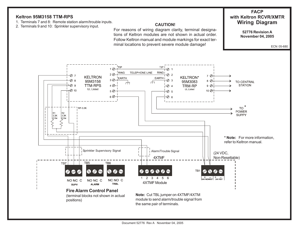
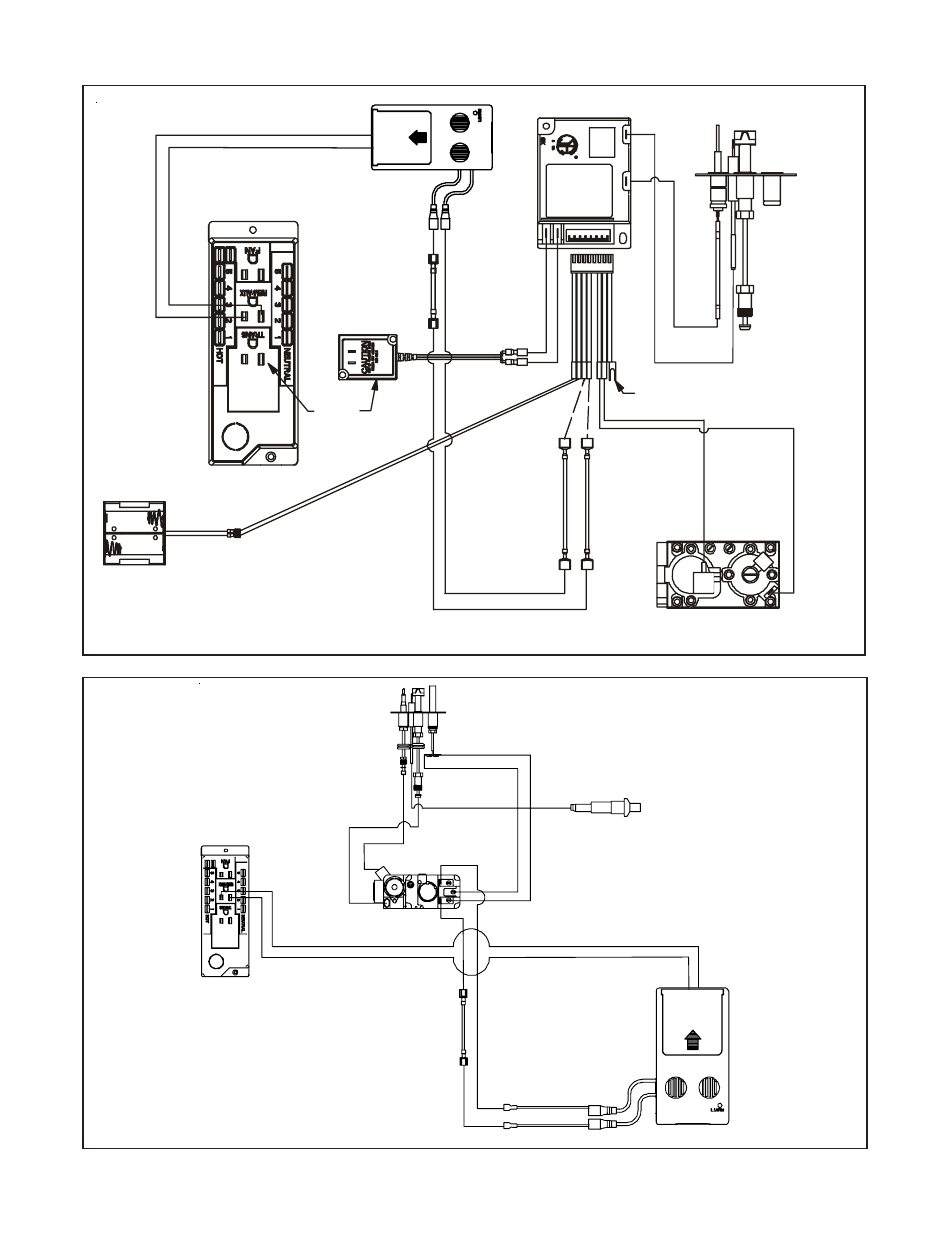
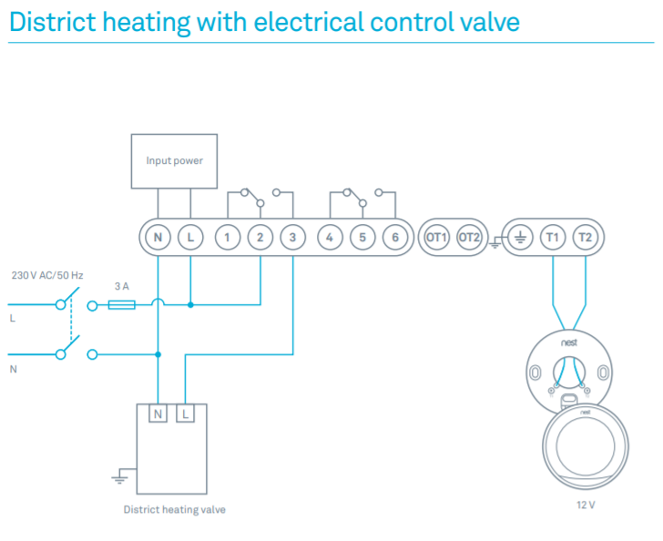
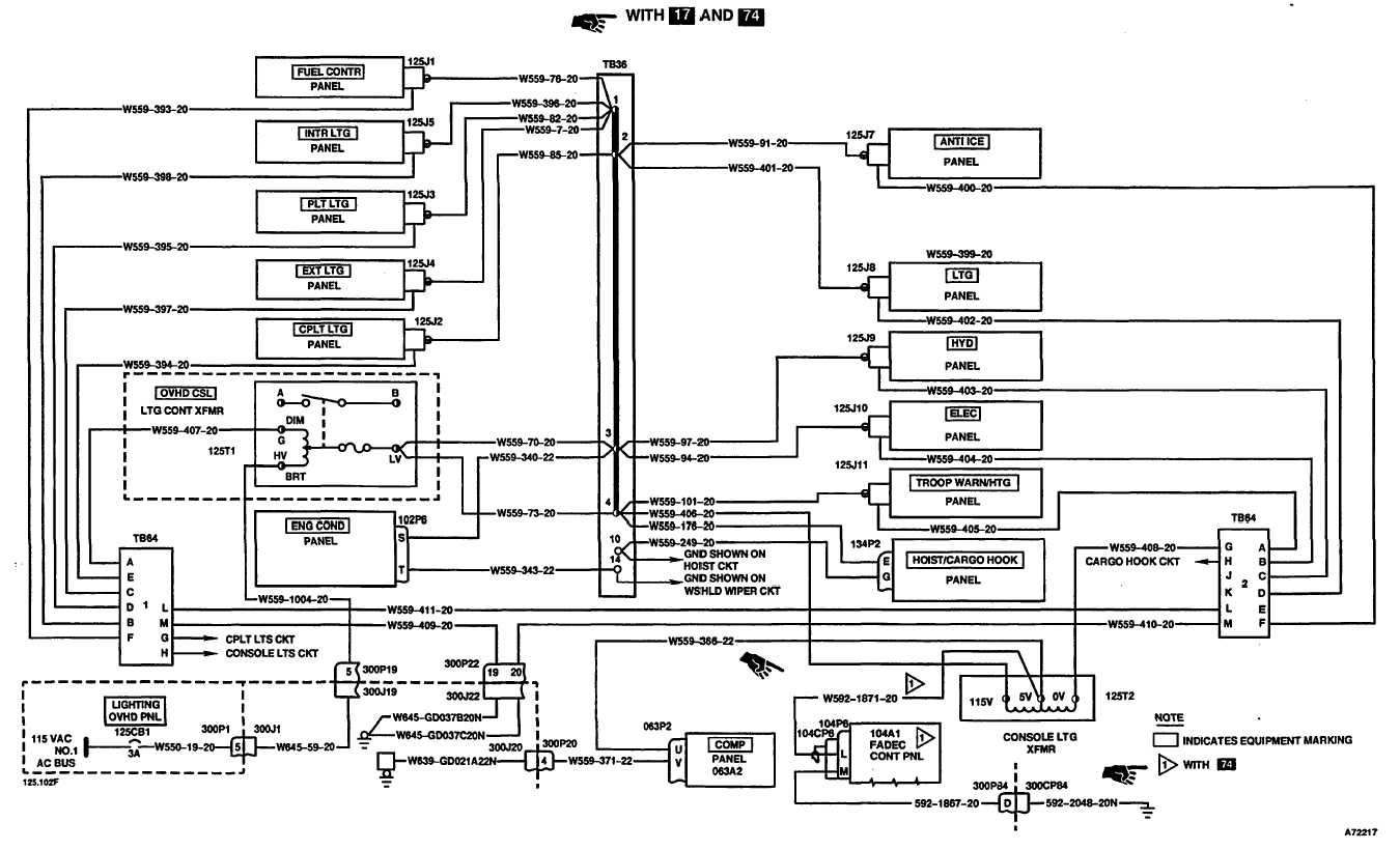
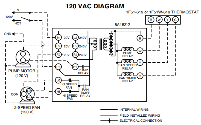
Only sync two remotes per receiver. For wiring diagram, see LIP Sheet Fig. 1.
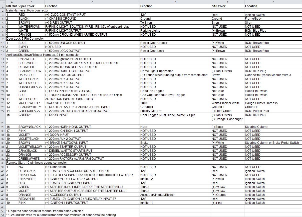
The cabin wiring can be the usual Romex type used for AC. The ground wire in that would be connected to the ground buss connection. When using Romex the black is considered + in a DC system, the white is the negative and the bare copper, sometimes green, is the ground.Control a Fog Machine – Electronicsford flex Car Alarm Wiring Information
