Connection. 2x Lead wires 26AWG.
Motor . Thermistor Speed Control (wire).
05 . PWM Input ODAPLL*B.
38 KDPTB1. OD As used in this operating manual, the terms „right“, „left“, „front“ and „rear“ indicate the sides of the bz.
OPERATION MANUAL. 1.
Clamping hazard imminent danger of being pressed. up. Drained amount is ca 24 l ( gal U.S.).
AN Application Note Rev. 2 The SOIC is a surface mount integrated circuit package. .

Cross-Section of EP Package with Heat Transfer Schematic. Indicate “TB” (Terminal Ball Bearing), “WB” (12” Wire Leads, Ball ODAPL- 24L*B. 2, . DC Fan Option Diagrams KDPTS2.
DPS/MRPU/INRPK/CAP//PT 1. Scope of supply: 2. Supply and installation of Tripod turn stile gate Suitable for item no ..
40”W x 90”H. Body monitoring station size approximately 24”L x20”W x 77”H.
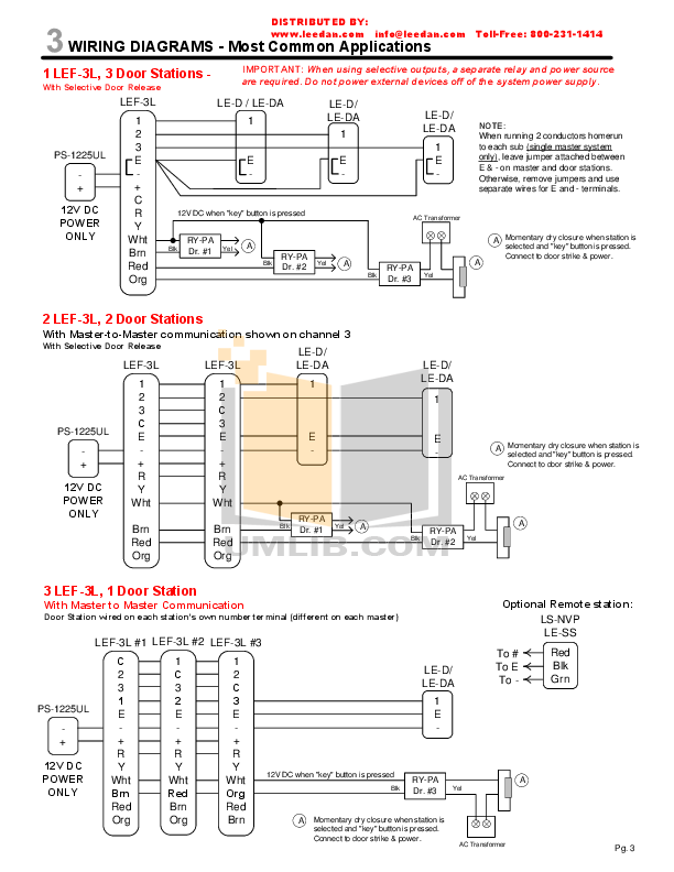
Bidder is required to submit technical datasheets (including circuit diagram and wiring details) of all.Wiring Class Class 2 Description The DNSL is a LINKnet-only network sensor with a temperature sensor, a customizable LCD display and 4 push buttons for user control. Both the LCD display and the push buttons are fully programmable via GCL+ over the LINKnet network.
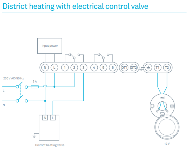
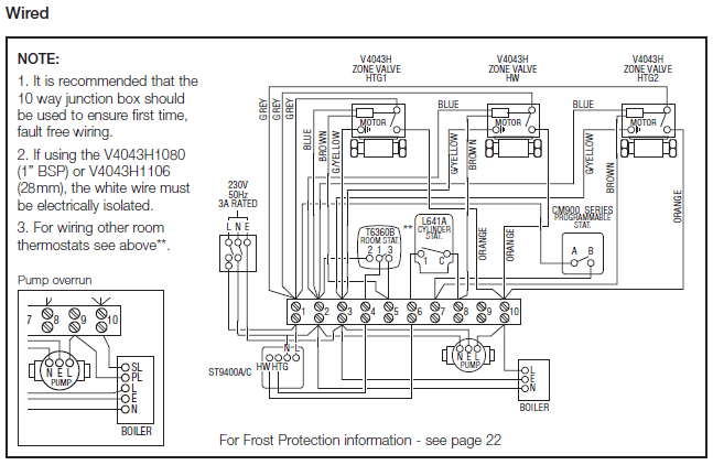
Application The DNSL is used for applications that require one or more low. vin id; wiring diagrams for the volvo non turbocharged models from modelyear until modelyear part 2 of the volvo wiring diagram.
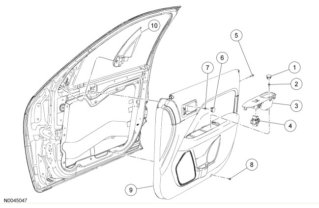
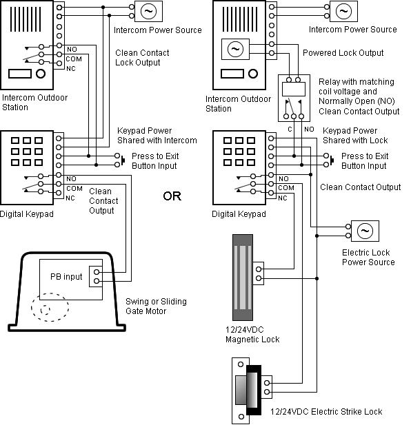
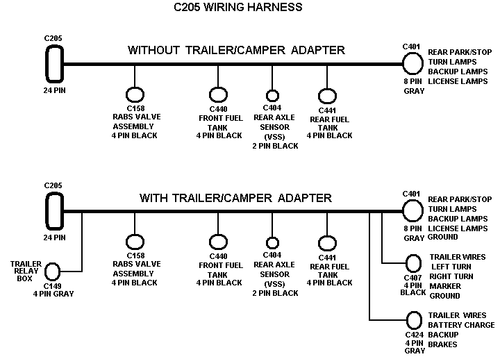
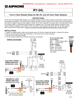
Volvo system wiring diagrams volvocluborguk, system wiring diagrams volvo 24l, engine performance circuits (1 of 2) volvo system wiring diagrams author. View and Download Aiphone DOOR RELEASE RELAY MODULE RYL user manual online.
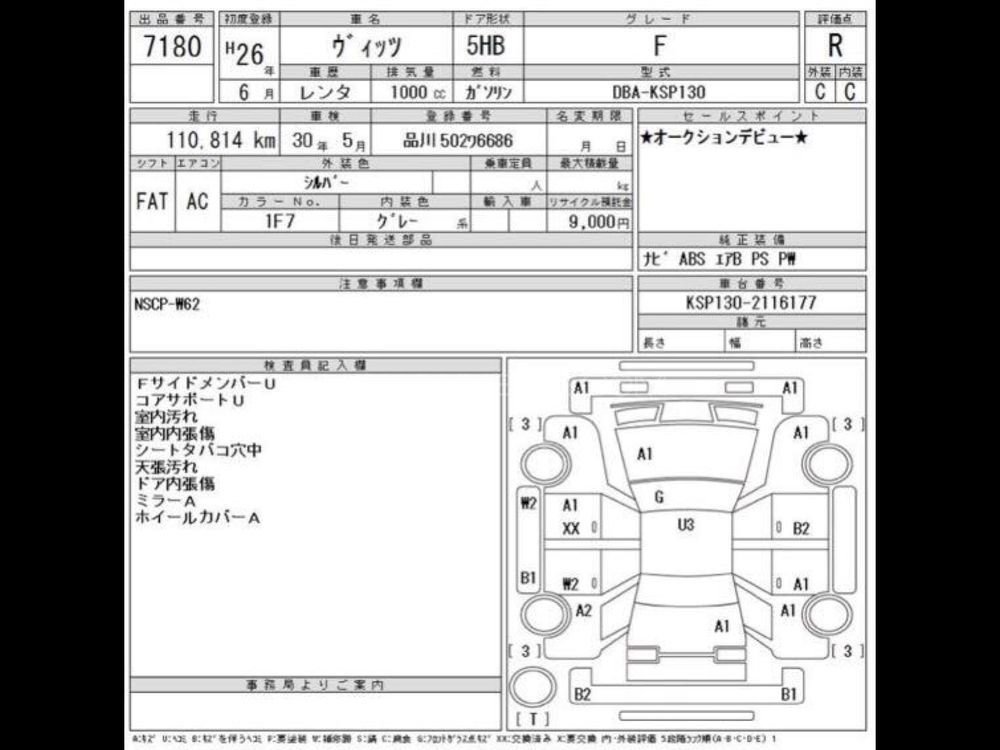
Form C Door Release Relay for AX, KB, KC, and JA Color Video Systems. DOOR RELEASE RELAY MODULE RYL Intercom System pdf manual download.
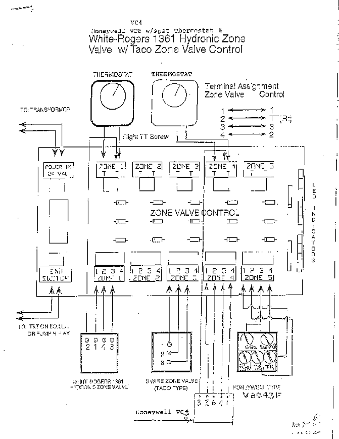
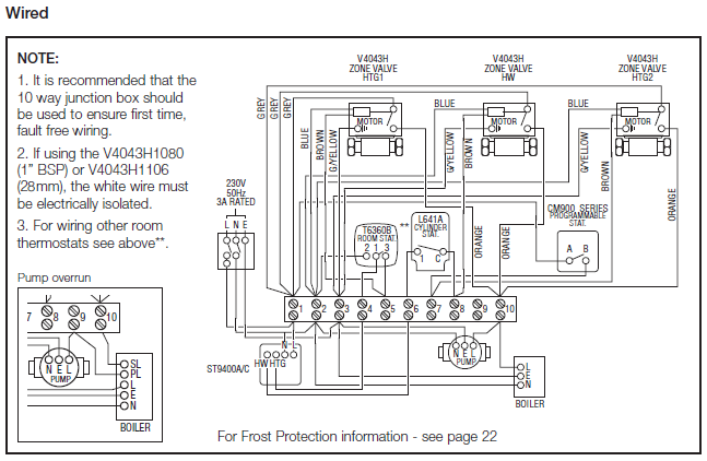
Electrical Wiring Diagrams
The RYL Door Release Relay Module is an interface between the door strike contacts on the Aiphone monitor and the actual release mechanism. The contact closure directly out of the monitor is ra ted at 12V AC with a low current capacity.
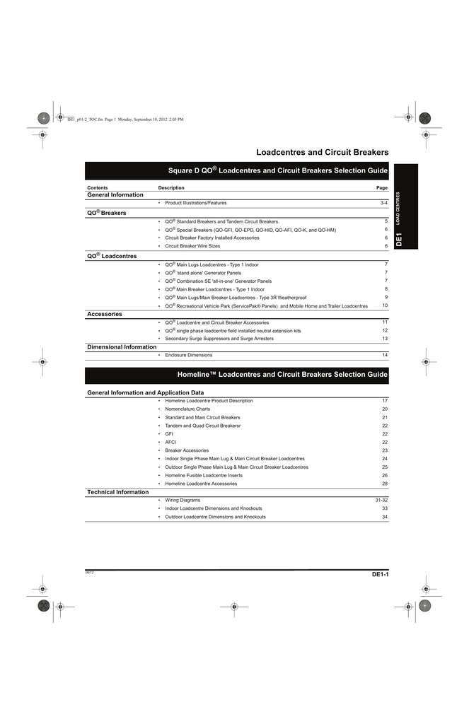
If your strike or maglock requires more voltage or current, the RYL . Electrical Wiring Symbols.
When looking at any switch diagram, start by familiarizing yourself with the symbols that are being used. The electrical symbols will not only show where something is to be installed, but what type of device is being installed.Duramax Wiring Diagram | Wiring LibraryElectrical Wiring Diagrams
