The Manual must remain with the engine/aircraft in case of sale.
In this Manual the installation of all ROTAX Series engines is. the installation and modification of their aircraft’s electrical system.
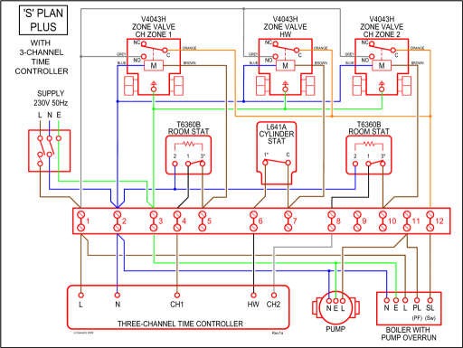
dependent engines (Rotax iS, UL Power, etc), those with electronic Note that a wiring diagram shows you how the components connect together. The Manual must remain with the engine/aircraft in case of sale. ..
This section describes the installation of engine type ROTAX Series. ROTAX UL. Aircraft Engine v WARNING.
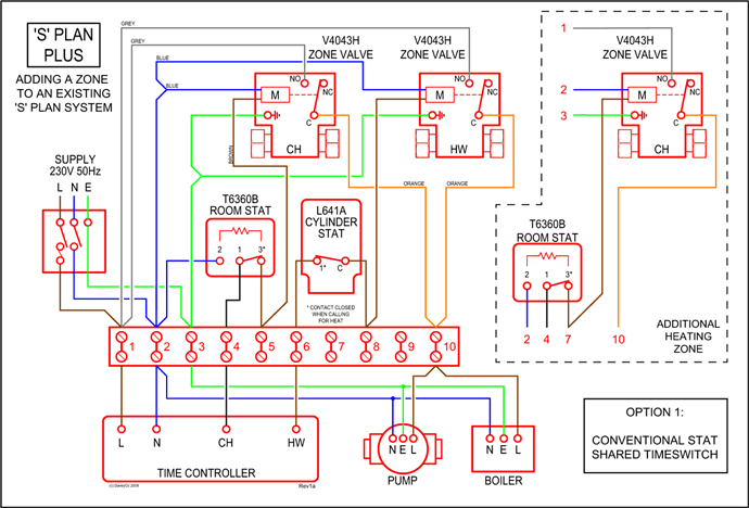
Before starting with the engine installation, please, read the Instal- lation Manual completely as it. Manufacturer’s Data for Amateur Airplane Builders Series Installation Manual · Rotax Dual Alternator Electrical (Diagram) · Rotax Alternator-Ignition.Feb 05, · Myself and 3 of my co CH builders have been planning to install the Rotax iS in our CHs since the day that Rotax announced the release of the iS.
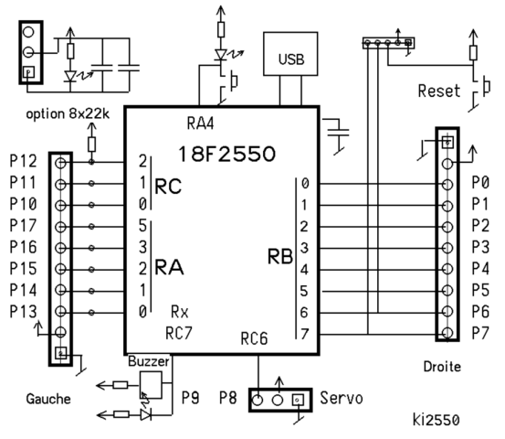
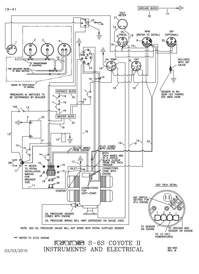
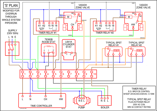
can be mounted farther from the engine. See the above wiring dia-gram (page of the current Rotax S installation manual).
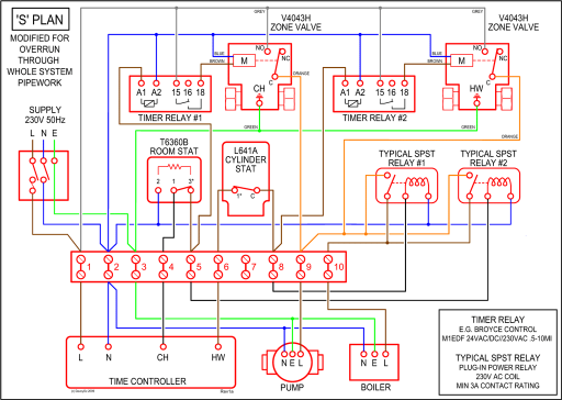
This diagram is quite good and needs only two points of clarification. 1.
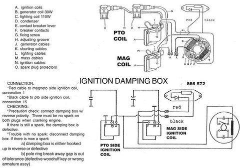
The positive charging wire, referred to as (battery +, consumer on the Rotax wiring diagram), which is con-. Rotax iS Ignition System 1. Is it possible to isolate the Battery and use a dedicated charger powered into the VPX in flight and switch to V AC on the.
Nov 18, · Mark Paskevich of Rotach Research Canada Ltd. (the Canadian Rotax distributor) explains the new fuel-injected Rotax iS engine installation developed for the Zenith STOL CH Rotax iS Wiring Harness.
Explanations of symbols and statements in part number charts: N = Newly introduced part number ; s.v. = Still valid.
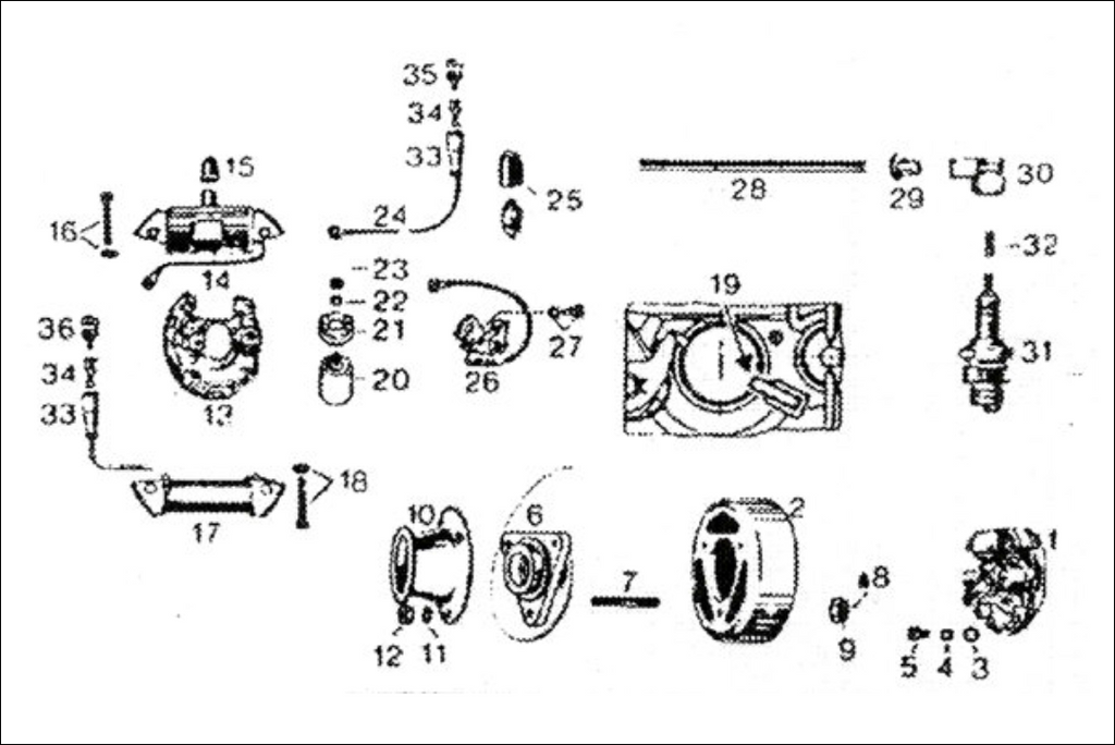
Part was replaced by compatible component and can not be supplied any longer by the producer.AeroElectric Connection – Manufacturer’s Datais Wiring Presentation – Engine/Rotax – CT Flier Forum