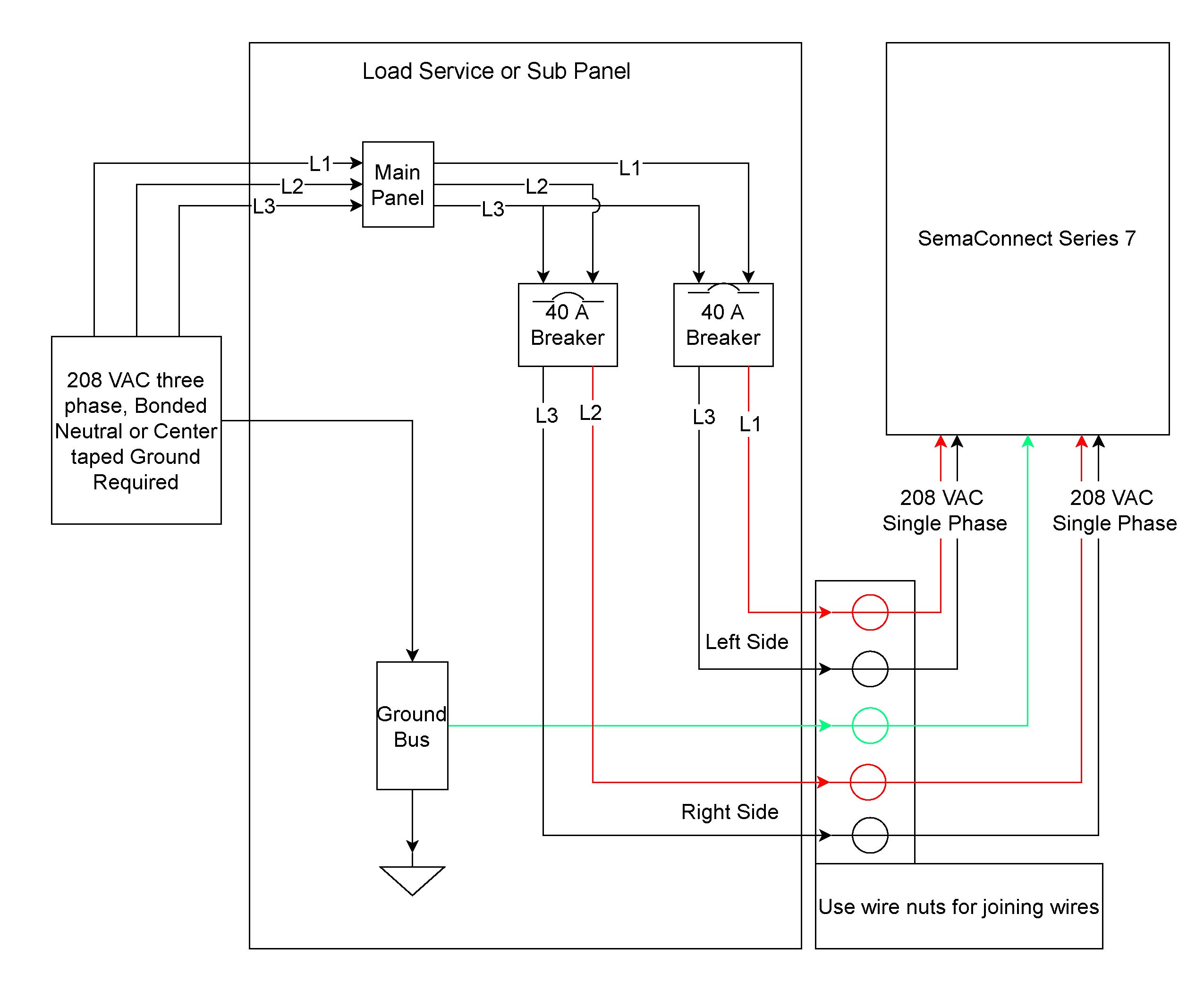
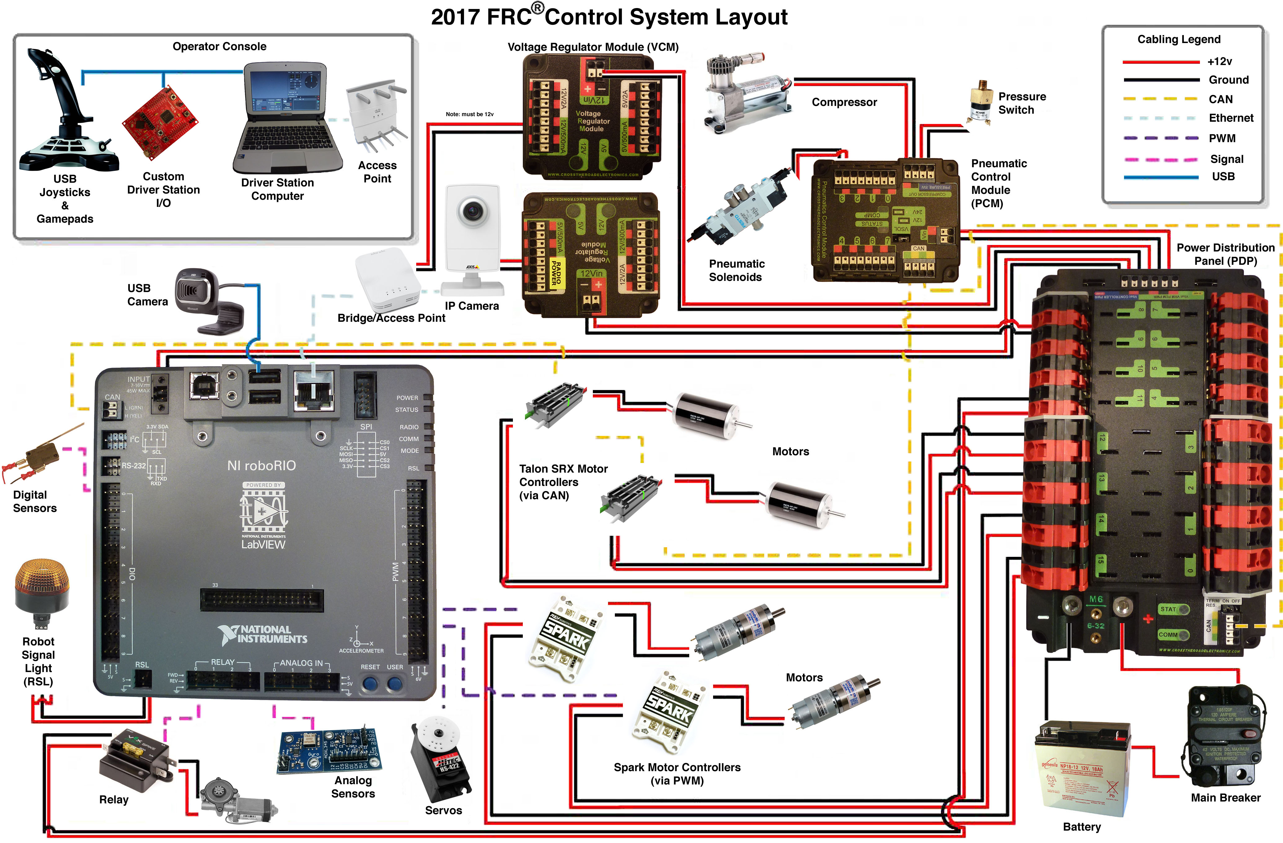
The roboRIO · General The CAN Bus · Appendix A: General Wiring Diagram When wiring, we recommend twisting the two wires together. I am looking for a wiring diagram more detailed than this for the Banner . White or Black goes to the SIG pin of a DIO port on the roboRIO.
. sees a reflection; the Black wire is active when the sensor does not see a reflection. Know the Block Diagram.
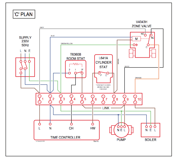
1. For FRC, consider breaking block diagrams into “ power” avoid loose wires, make sure no wires will interfere with moving parts. navX-Micro may be connected to the RoboRIO via several methods.

One-wire Connect via USB cable. By using a USB Mini-B type (Male) to USB A type (Male) connector, navX-Micro can receive both power and also communicate As shown in the diagram below, the RoboRIO MXP Connector’s I2C-related pins are .
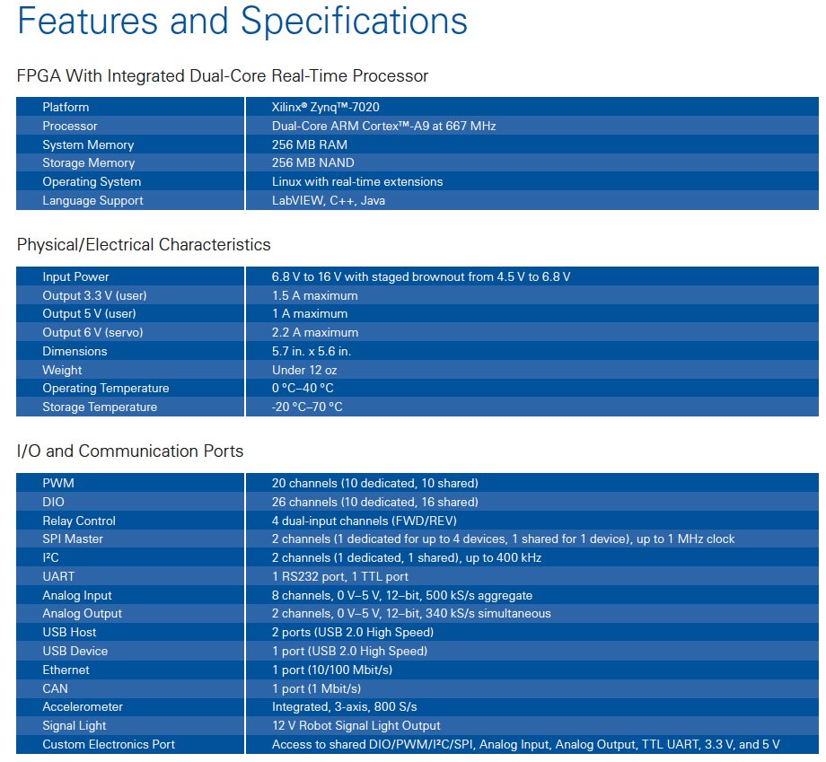
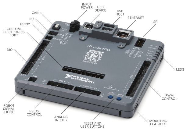
The first PCM on your robot can be wired from the PDP VRM/PCM connectors on the end of the PDP. The PCM is connected to the roboRIO via.USER MANUAL NI roboRIO RIO Device for Robotics The NI roboRIO is a portable reconfigurable I/O (RIO) device that students can use to design control, robotics, and mechatronics systems used in the FIRST Robotics Competition (FRC). Wiring diagram and layout should be similar for other motor controllers.
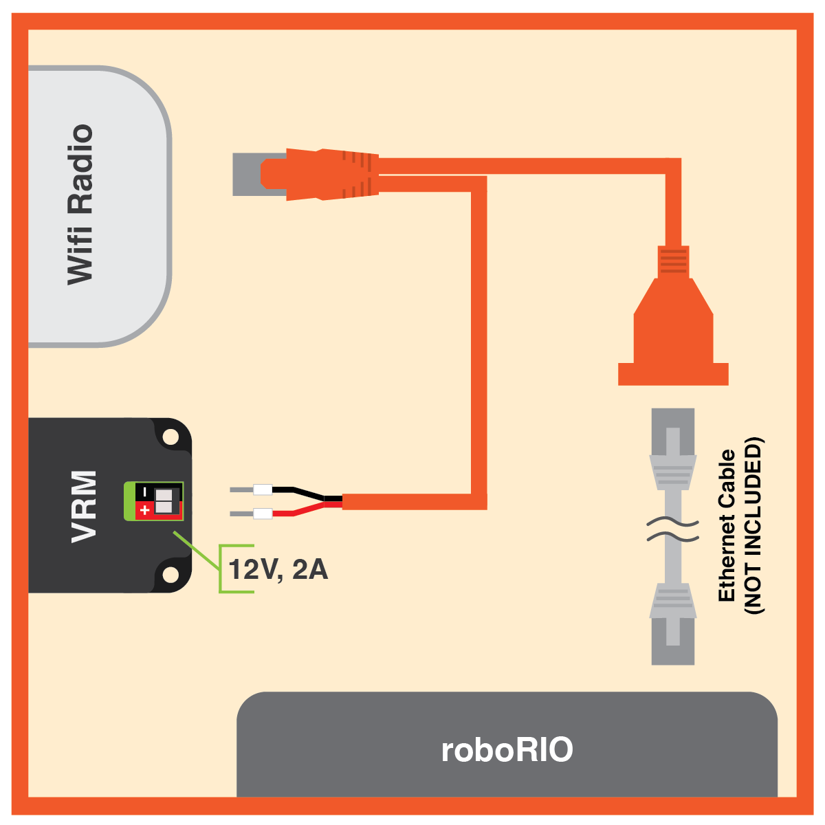
(Ethernet) port on the roboRIO. Wiring the FRC Control System Page RoboRIO to PCM CAN Requires: Wire stripper, small flat screwdriver (optional), yellow/green twisted CAN cable.
Wiring the Talon SRX Signal Input Configuring a Talon SRX with CAN bus on a roboRIO Talon SRX automatically detects CAN bus traffic so there is no need to select “CAN” vs “PWM”. The entire CAN bus harness.
To do this, connect a yellow signal wire to the NI roboRIO CAN terminal. Talon SRX – User’s Guide.
4. Insert the wire into the crimp and squeeze hard enough to fully crimp onto the wire, and release.
Do not crimp onto the insulation of the wire. 5.
Push the heat shrink over the exposed wire and crimp and use the heat gun to shrink it enough to be secure. 6.
Repeat on the second wire. lines used, must have at least two wires for the di fferential signals (CAN_H, CAN_L) and one wire for the reference potential CAN_GND.
If a shielded line is used, the shield should be assigned to.Chief Delphi – Upgraded FRC Control System Wiring DiagramGeneral roboRIO Overview | FRC Electrical Bible