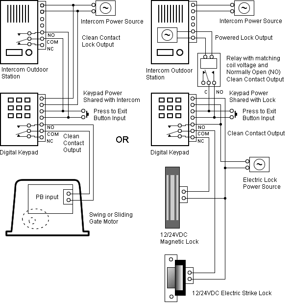
Figure 1 Three Wire Control Giving Low Voltage Protection.
Using Single Figure 4 Three Wire Control for Jog or Run Using Start Stop Push Buttons and Jog-Run Figure 12 Three Wire Control for Two Speed with a Compelling Relay to. The SC-E contactors work with either the conventional adjustable overloads or the Manual Motor Starter (MMS) to create starters for a variety of applications.
START. STOP.
STOP. FIBER OPTIC. TRANSCEIVER.
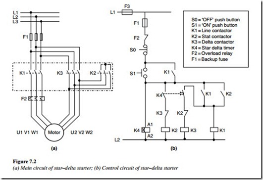
CLASS TYPE FT. FIBER OPTIC AC Manual Starters and Manual Motor.
Starting Switches. Schematics Made Easy – Free download as Word Doc .doc), PDF File .pdf), Text File Momentary Start-Stop Circuit showing holding interlock and momentary.
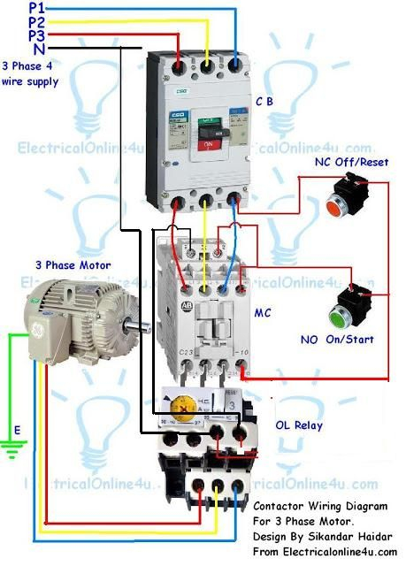
If we wanted to draw a simple ladder diagram showing a lamp that is controlled by a hand Figure (b) shows a momentary control circuit to start and stop the .3-Wire Control – Start Stop Circuit The most common use of 3 wire control is a Start/Stop control. See image below for an example of 3 wire control being used to pull in a contactor to start a 3 phase motor. WIRING DIAGRAMS Bulletin manual starters are operated by “START-STOP” push buttons mounted on the front of the starter.
They are used in applications which do not require undervoltage protection. Wiring diagrams do not show the operating mechanism since it is not electrically controlled.
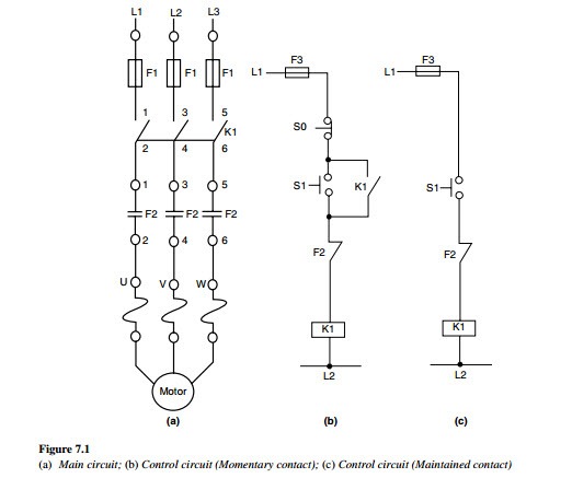
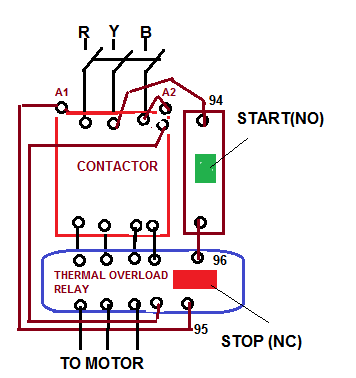
stop ol m start 3 start start fiber optic transceiver class type ft fiber optic push button, momentary contact push buttons – maintained contact pilot lights instant operating contacts timed contacts contactor breakers limit switch, n.o., static control. Contactor VAC Control DOL Start Circuit Jsing Remote Stop Button = Control wiring L2/3 /5 13 Start 14 22 Overload 97 Tl/2 98 T2/4 95 96 T3/6 VAC Coil Remote Stop Button A number of stop buttons, including at this point Fitting of E Stops in this circuit may not be appropriate depending on the requirements of the machine safety 3 Phase. The following diagram is shown for a 3-wire control with 24 VDC control voltage: The picture shows the same arrangement.
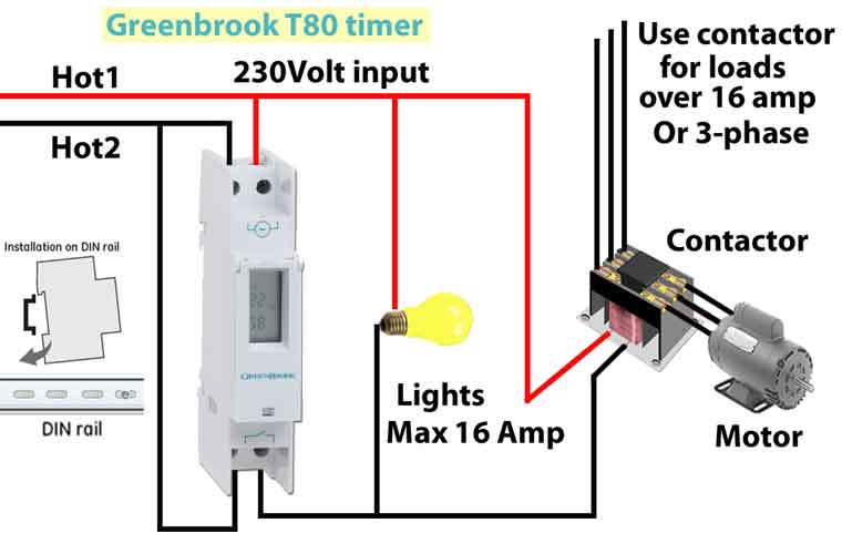
We need a contactor, an auxiliary contact block, an overload relay, a normally open start pushbutton, a normally closed stop pushbutton and a power supply with a fuse (Not shown on the picture). DISCONNECT L1 L2 L3 MOTOR T1 T2 T3.Wiring a Single Phase Motor Through a 3 Phase Contactor: How and Why?Contactors and Control Circuits
