FFAP, FFWP and FPAK Line Copeland Scroll air-cooled and water-cooled condensing units
X-Line Copeland Scroll™ Outdoor Refrigeration Units. DS-4_X-Line. 1/16 ERFTAD. 1/2 S. /8 S.
Copeland condensing unit selection guide for commercial ref
C3AMCAV. . Physical and Electrical Data Copelametic™ air-cooled condensing units.
Model FJAL TXV Superheat Adjustment Chart . FGAH-ACFV.
Circuit Amps: ; Max. Fuse Size: 25; Suction Conn.: 7/8″ ODF; Liquid Conn.: 3/ 8″ ODF; Pressure Control: Low; Receiver Capacity Lbs.: ; Length: “;. For more free Copeland literature please visit www.
Electrical Connections . A. 1.
F3AM-ACFV, TFC. 1.
Electrical Connections. Fan Cycle . Copeland™ Hermetic Compressor and . 3 /4. 3, 4, 4, 5, 5, M2FMCFA, CFV.
a. 3/4.
Copeland condensing unit
Head. Pressure.
Control Valve. Fan.
Cycle. Control.
Water. Valve.
. .
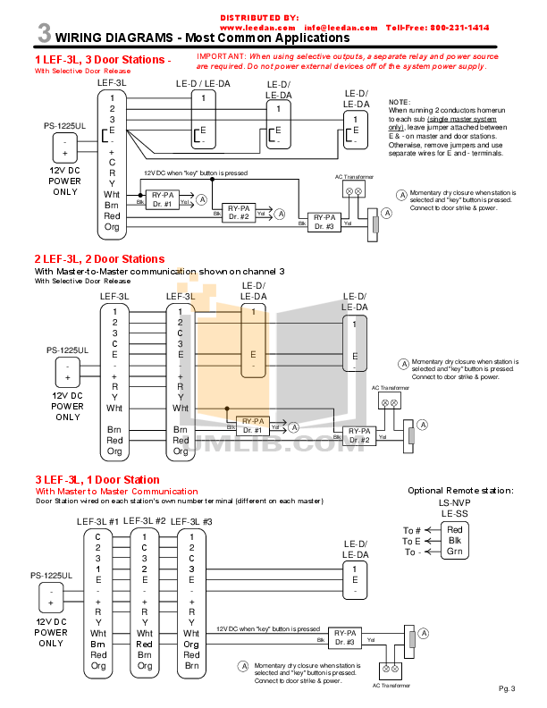
Copeland Scroll™ air-cooled and water-cooled condensing units Less Leaks, Reduce Callbacks, Lower Installation Cost, FJAL-ACFV.Welded Compressors Wholesaler Product Guide C A R. For more free Copeland \rliterature please visit. schematron.org Electrical Diagrams Compressor Drawings Typical Drawings Copeland® Brand to Copeland® Brand Quick Reference.
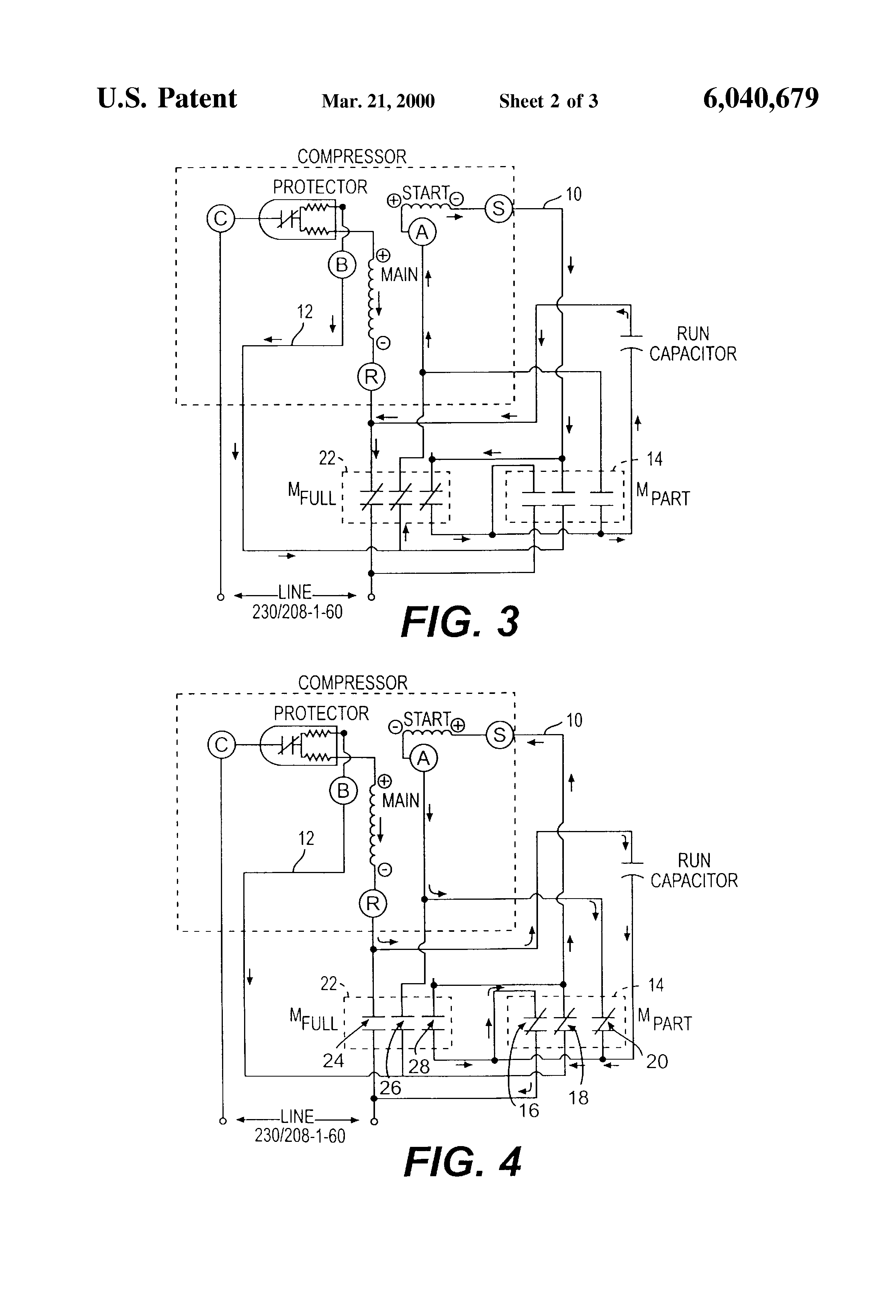
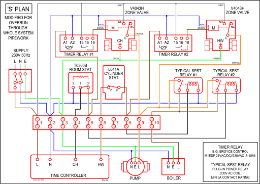
Carrier/Carlyle 6D/06D Compressors Terminal Wiring Diagrams Control Circuit L1 L2 Start Capacitor Run Capacitor Start Relay Common Overload Compressor Terminals Red Yellow Blue Orange Orange Single Phase 3 Leads 1 OverLoad Red Orange Blue Yellow Control Circuit Compressor Terminals Contactor L1 L2 L3 Control Circuit L1 L2 L3 Contactor Overloads.
field power wiring marked terminal plug and receptacle schematic diagram single supply circuit yel blu blk relay 3 22 vdc coil t d r relay 2 22 vdc coil t d r brn brn gry red htr6 blu 8 ls6 yel 6 blu ls5 htr5 blk 2 relay 3 htr4 blk 8 ls4 6 htr3 blu 4 ls3 2 relay 2 blk htr2 blk 8 yel yel ls2 6 blk htr1 4 ls1 2 relay 1 yel field power wiring see.
DWM Copeland™ semi-hermetic compressors are manufactured according to the latest European and US safety standards. Particular emphasis has been placed on the user’s safety.
These compressors are intended for installation in systems according to the EC Machines directive. Discontinued wiring diagrams listed in the back of this section are for compressors that are no longer available by Emerson Climate Technologies, Inc. The replacement wiring diagram is not necessary the same as the old wiring diagram show in the front of this section.
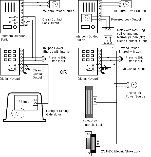
Use caution when selecting the appropriate wiring diagram.Copeland condensing unit – PDFE | Copeland Refrigeration | FFAPZ-CFV | Johnstone Supply