Green wire – to “Tach” output on ignition box or to negative side of coil on non- electronic points systems. NEVER connect directly to a plug or coil wire! Black wire.
The electronic speedometer in this instrument is designed to operate with an electrical speed sender. The speed sender signal range must be between Green wire – to “Tach” output on ignition box or to negative side of coil on non- electronic points systems.
NEVER connect directly to a plug or coil wire! Black wire.
Also the model name CFB and down is wiring diagram that could Digital LED Tachometer RPM Speed Meter with Hall Proximity Switch. I too purchased one of these Tacho’s and it came with no wiring info.
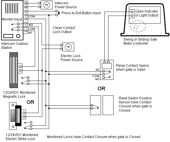
pressing the vendor eventually received this comprehensive diagram.INSTALLATION INSTRUCTIONS 5″ Tachometer Rev. B QUESTIONS: If after completely reading these instructions you have questions regarding the operation or installation of your instrument(s), please contact Auto Meter Technical Service at You may also email us at [email protected] Tachometer Installation and Operation Instructions For Street Eliminator, Comp Eliminator, Pro Eliminator, and Top Eliminator Tachometers THE INSTRUCTIONS FOR INSTALLATION AND ELECTRICAL WIRING FOR THESE TACHOMETERS FOLLOW.
USE IS RESTRICTED TO 12 VOLT NEGATIVE GROUND ELECTRICAL SYSTEMS. Item Description Quantity Parts List 1.
Tachometer . Tachometer Installation and Operation Instructions For Street Eliminator, Comp Eliminator, Pro Eliminator, and Top Eliminator Tachometers THE INSTRUCTIONS FOR INSTALLATION AND ELECTRICAL WIRING FOR THESE TACHOMETERS FOLLOW.
USE IS RESTRICTED TO 12 VOLT NEGATIVE GROUND ELECTRICAL SYSTEMS. Item Description Quantity Parts List 1. Tachometer . Disconnect the boat’s battery.
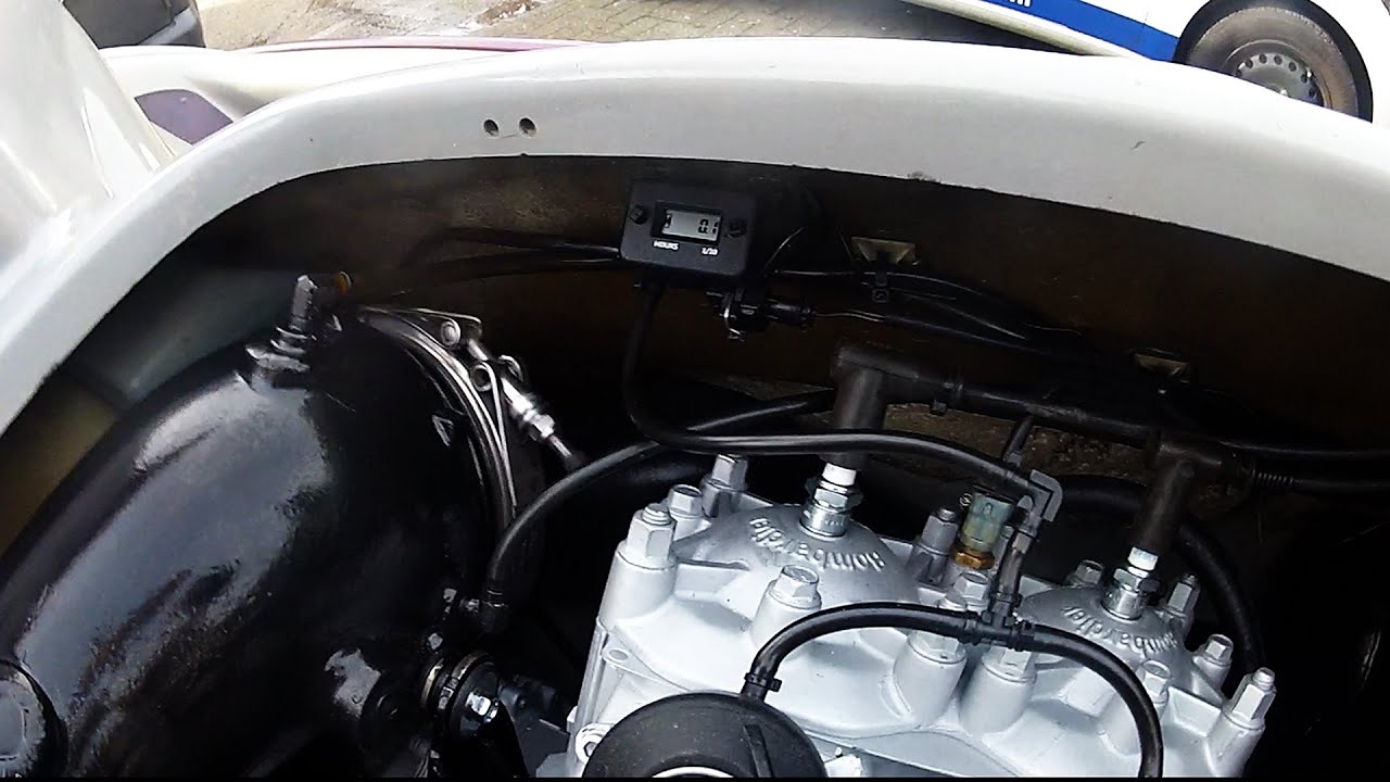
Strip 1/2-inch of insulation from both ends of all the wires. Use a pliers-type crimper to crimp ring connectors to both ends of the one of the red wires and the black wire and one end of each of the gray wires. Installation of the Autogage Tachometer was fairly simple with only minor wiring including a wire to the distributor, a good ground, a 12 volt switched power source and a wire to power the tach’s light.RPM Counter connections | Model EngineerTachometer Installation Autogage Tach Install
