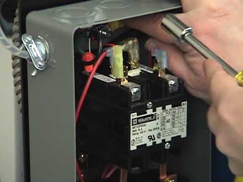
Motor control start stop station.
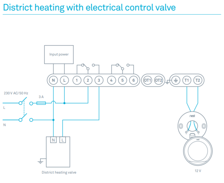
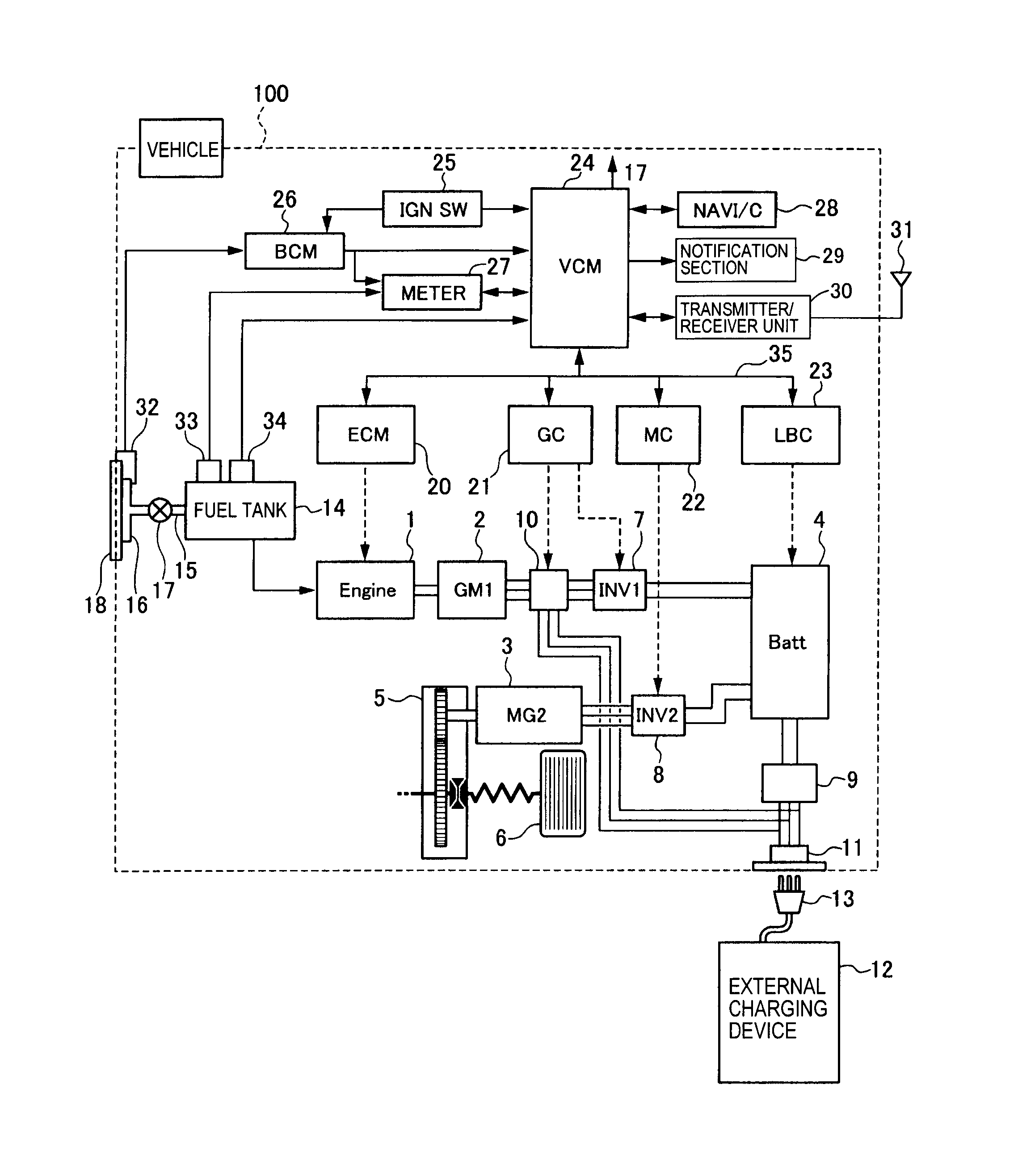
Motor control wiring diagram. How to wire start stop station to control three phase motor. Motor control circuit.
Can anyone help me find any diagrams of wiring the motor controls. humberguy is offline is this a self-contained unit where the START and STOP buttons are built into the starter/contactor, or are the buttons a seperate unit?
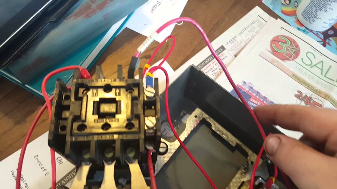
emolatur is offline push button for stop. One relay for control, and the motor.
Can anyone help me find any diagrams of wiring the motor controls. humberguy is offline is this a self-contained unit where the START and STOP buttons are built into the starter/contactor, or are the buttons a seperate unit?
emolatur is offline push button for stop. One relay for control, and the motor. Start Stop 3 Phase Motor Starter Wiring.

Thomas Shue’s World. Loading Unsubscribe from Thomas Shue’s World?
Motor Starter Wiring Diagrams
Cancel Unsubscribe. Can anyone help me find any diagrams of wiring the motor controls.
Start Stop 3 Phase Motor Starter Wiring
humberguy is offline is this a self-contained unit where the START and STOP buttons are built into the starter/contactor, or are the buttons a seperate unit? emolatur is offline push button for stop.
One relay for control, and the motor.Whenever we need to start and stop the motor from more than one point, then we may expand it through push buttons in the motor control circuit (for example, You may use this alternative power control wiring diagram of controlling a three phase motor from mo re than two places). A wiring diagram gives the necessary information for actually wiring-up a group of control devices or for physically tracing wires when trouble-shooting is necessary. A line diagram gives the necessary informa- tion for easily following the operation of the various devices in the circuit.
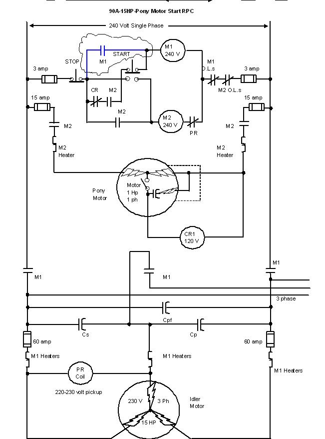
Typical Wiring Diagrams For Push Button Control Stations 3 Genera/ Information @ Each circuit is illustrated with a control circuit (continued) schematic or line diagram and a control station wiring diagram. l The schematic or line diagram includes all the components . Whenever we need to start and stop the motor from more than one point, then we may expand it through push buttons in the motor control circuit (for example, You may use this alternative power control wiring diagram of controlling a three phase motor from mo re than two places).

PUSH BUTTON, SELECTOR SWITCH, LIMIT SWITCH, ETC. FIBER OPTIC CABLE ELECTRICAL CONNECTIONS MOTOR 3CT TO V SEPARATE CONTROL * OT is a switch that opens when an overtemperature condition exists (Type MFO and MGO only) T1 T3 WIRING DIAGRAM.
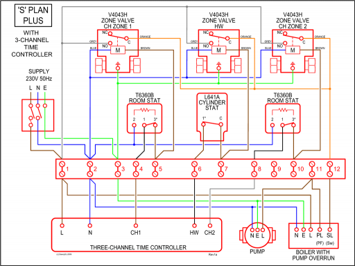
M A1 A2 M.Motor Starter Wiring Diagrams – schematron.org Knowledge Base (Wiki)Motor Starter Wiring Diagrams – schematron.org Knowledge Base (Wiki)