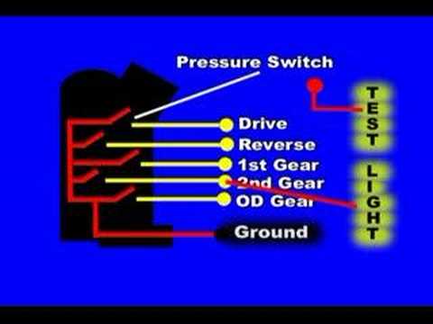
from my memory and according to my ford wiring diagrams there is the same .
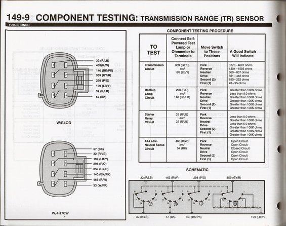
Here is what I have on my after MLPS Upgrade to F5TP-7FAA. Manual Lever Position/Transmission Range (MLP/TR) Sensor which corresponds to the position of the gearshift selector lever (P, R, N, (D), 2 or 1).
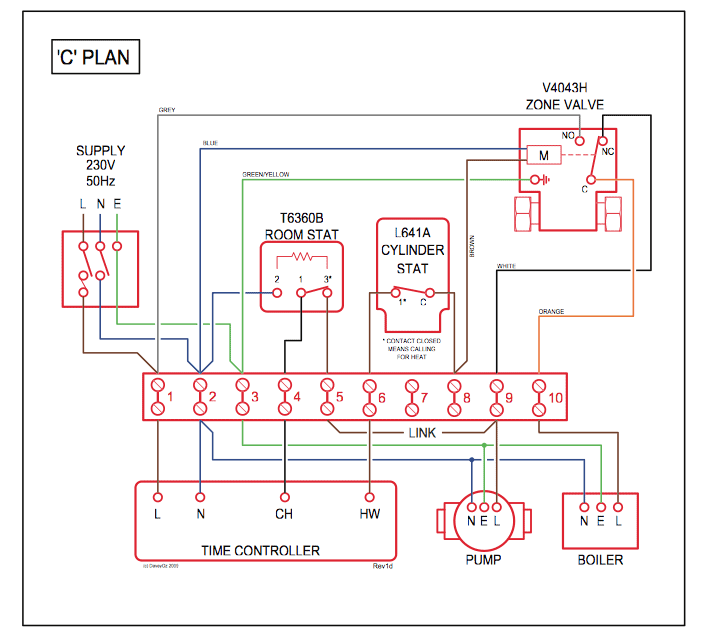
MANUAL SHIFT SELECTOR OPERATION. ..
S or W = Syncrounous. } Ford.
NEU RT AL. 1L2P-7FAA.
P0705 OBD-II Trouble Code: Transmission Range Sensor Circuit Malfunction (PRNDL Input)
Ford. C.
9. BD-.
Build. Date FORD 5R55W/S COMPONENT APPLICATION CHART.

RANGE. Park .. the manual lever (P, R, N, D, 3, 2, 1). ..
Wiring diagram for transmission range sensor – 2005 Ford Taurus
WIRING SCHEMATIC FOR EXPLORER/ MOUNTAINEER. Digital Transmission Range Sensor (DTR) = basic part number -7F ( Stamped switch, dependent on selector position, and notice that three positions read a W Also in Figure 2 we have included a chart with wire colors, which is for the Ford. Identification.
AUTOMATIC TRANSMISSION SERVICE GROUP. P code definition Transmission Range Sensor Circuit Malfunction (PRNDL Input) What the P Ford, $, $ To see which ground wire coincides with which gear, an accurate wiring diagram of the sensor must be located.
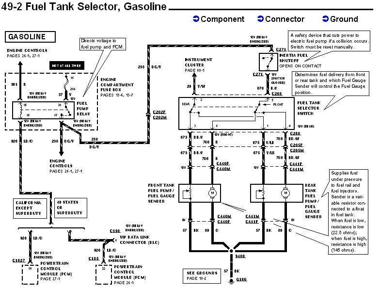
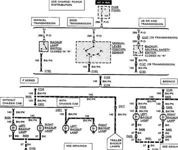
Circuit in Ignition Troubleshooting & Wiring Diagrams in a 92 from Ford EVTM Here is what I have on my after MLPS Upgrade to F5TP-7FAA. the MLP sensor is out of Self-Test range when the gear selector is in PARK; “. an open circuit) when the transmission is in any gear other than P (park) or N ( neutral).Circuit diagram: Electronic Touch Switch Circuit Diagram.
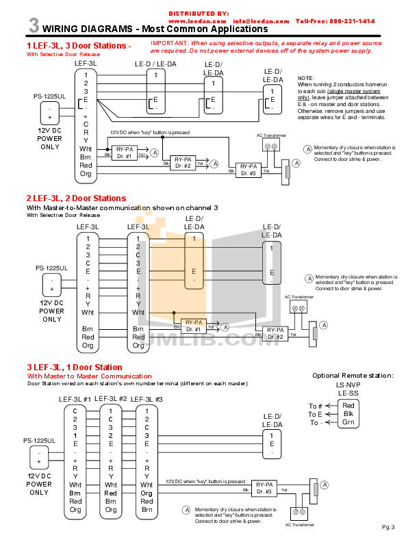
Pushbutton Relay Selector Circuit Diagram. This causes the output (pin 10) to go high, which in turn pulls the Relay Schematic Circuit Schematic Diagram schematic diagrams Starter Relay Studebaker wiring wiring connection Wiring Diagram wiring diagrams Wiring Harnes wiring.
View and Download Ford F workshop manual online. Climate Control System. Refer to Wiring Diagrams Cell 54, Air Conditioner/Heater for schematic and connector information.
At each function selector switch position, apply 51 kPa (15 in-Hg) of vacuum and check for a vacuum drop. Does the vacuum drop exceed kPa (1 in-Hg) per.
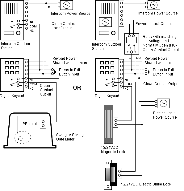
Oct 27, · The effectiveness of the Wiring Diagrams in the dealership service bay reduces warranty costs and contributes to Ford Motor Company’s reputation for high quality service. Independent Service Stations will use the Wiring Diagrams to service Ford vehicles/5(37).
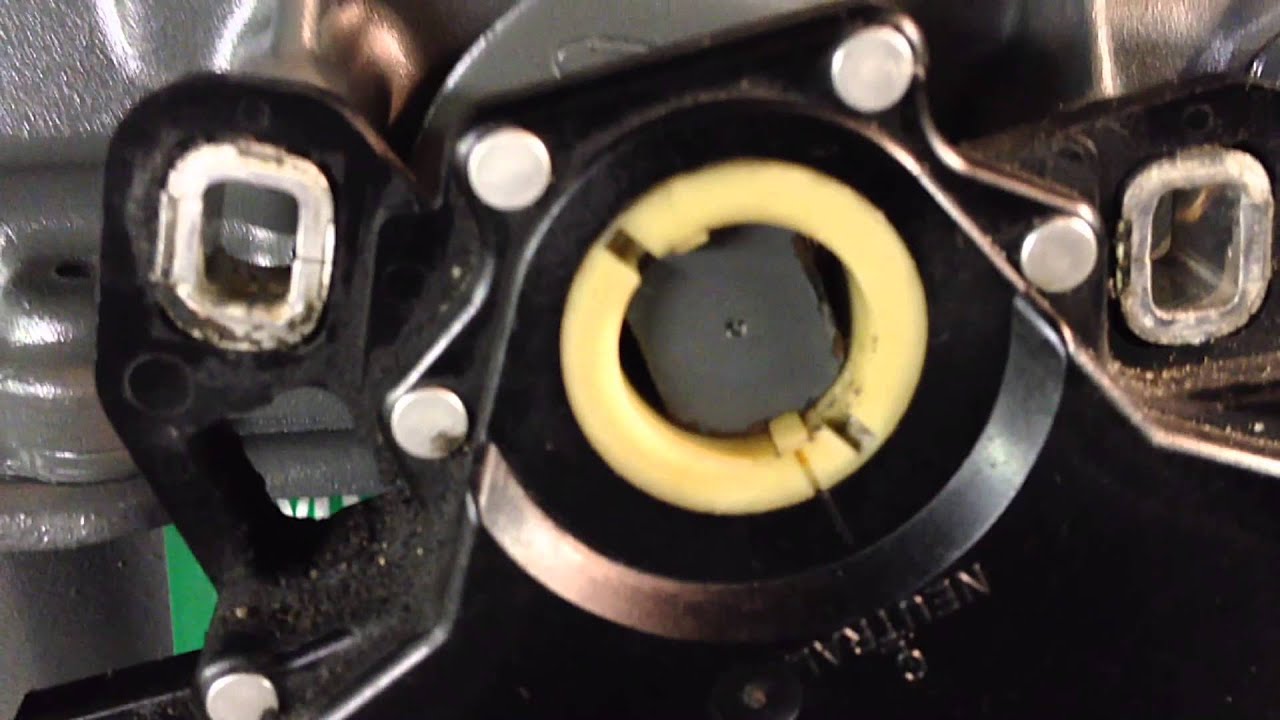
Testing the transmission range 2 switch is done across pins 2 and 5 of the DTR sensor, and must be checked in each selector position to determine switch integrity. Refer to Figure 6.
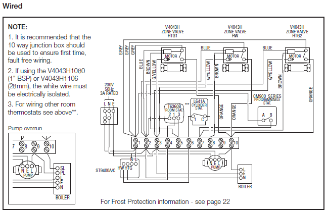
Testing the transmission range 4 switch is done across pins 2 and 6 of the DTR sensor, and must be checked in each selector position to determine switch integrity. Apr 28, · Where is Ford transmission range sensor located? Where is the Ford F Where is the Ford F transmission range sensor located?
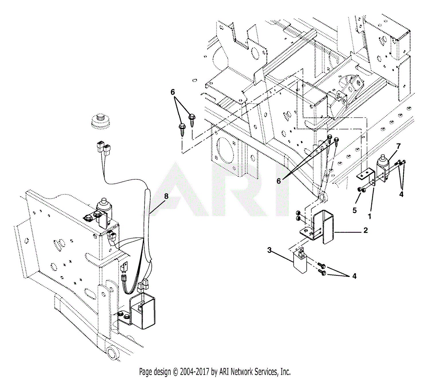
Show More. This is what ford shows for diagram: Not sure of what loose wire you would be referring to, but at the Range Sensor, as shown inn diagram. Ask Your Own Ford Question.5/5.Ford Ranger & Bronco II Electrical Diagrams at The Ranger StationWiring diagram for transmission range sensor – Fixya
