
A Honeywell WiFi thermostat is a smart device that allows you to control the temperature of your home remotely. It connects to your home’s WiFi network and can be controlled using a smartphone or computer. Installing a WiFi thermostat requires proper wiring to ensure it functions correctly and efficiently.
The wiring diagram for a Honeywell WiFi thermostat may vary depending on the specific model and the heating and cooling system in your home. However, there are some general guidelines to follow when wiring your Honeywell WiFi thermostat.
First, it is essential to turn off the power to your heating and cooling system before starting the wiring process. This will ensure your safety and prevent any damage to the thermostat or your home’s electrical system.
Next, identify the wiring terminals on your Honeywell WiFi thermostat and match them with the corresponding wires from your heating and cooling system. Common terminals include R (power), C (common), W/W1 (heat stage 1), W2 (heat stage 2), Y/Y1 (cool stage 1), Y2 (cool stage 2), G (fan), and O/B (reversing valve for heat pumps).
Wiring diagram for Honeywell Wi-Fi thermostat
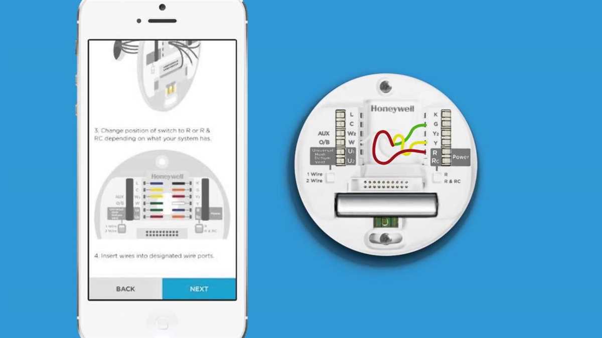
When it comes to installing a Honeywell Wi-Fi thermostat, having a proper wiring diagram can make the process much easier. The wiring diagram provides you with a visual guide of how to connect the thermostat to your HVAC system.
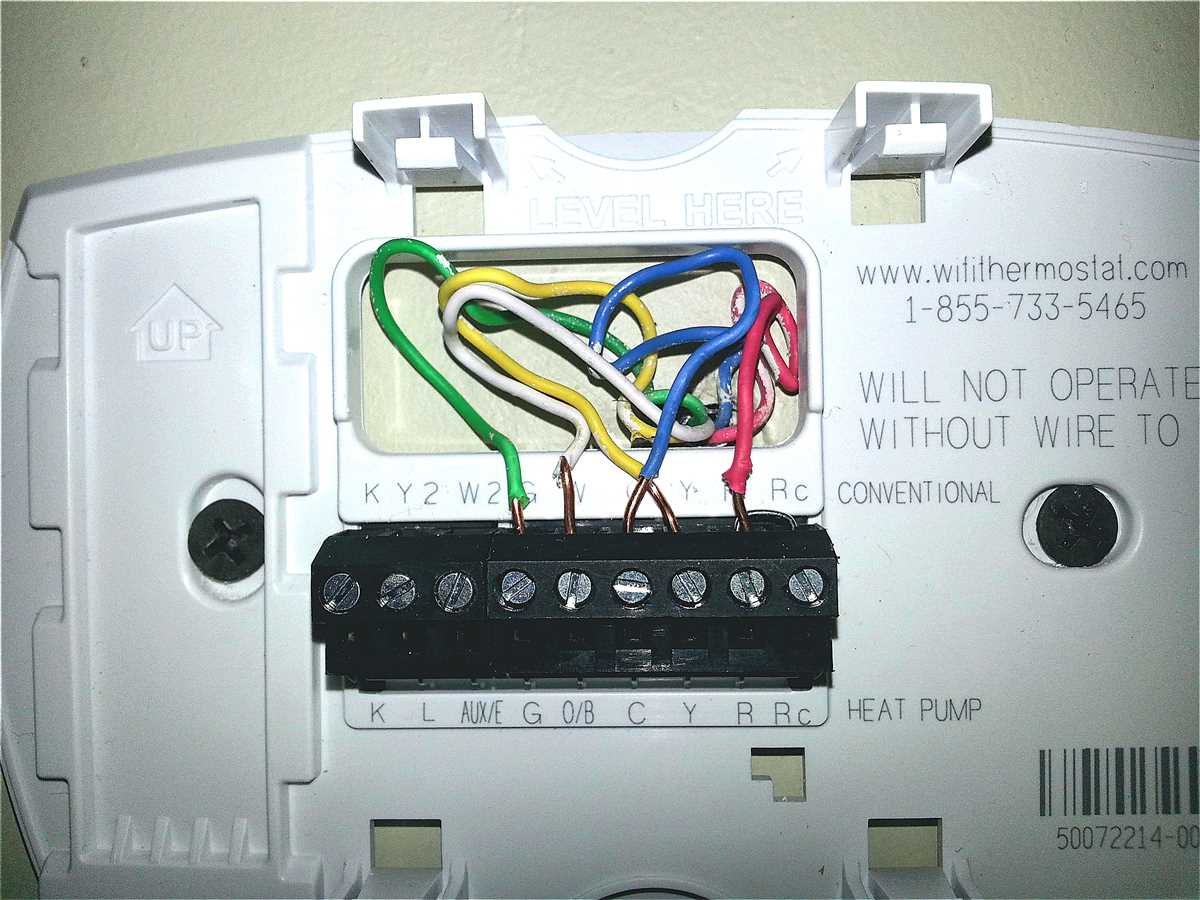
The Honeywell Wi-Fi thermostat typically has several terminals that need to be connected to specific wires. These terminals include R (power), C (common), W (heat), Y (cool), G (fan), and Rc (cooling power). The wiring diagram will indicate which wires from your HVAC system should be connected to each terminal on the thermostat.
For example, if your HVAC system has a red wire, it should be connected to the R terminal on the thermostat. The blue wire, typically the common wire, should be connected to the C terminal. The green wire, which controls the fan, should be connected to the G terminal, and so on.
It’s important to follow the wiring diagram carefully to ensure proper connection and functionality of your Honeywell Wi-Fi thermostat. If you are unsure about any of the wiring or have any questions, it is recommended to consult the installation manual or seek professional assistance.
Here is a basic example of a Honeywell Wi-Fi thermostat wiring diagram:
| Thermostat Terminal | Wire Color | HVAC System Terminal |
|---|---|---|
| R | Red | R |
| C | Blue | C |
| W | White | W |
| Y | Yellow | Y |
| G | Green | G |
| Rc | Red | R |
Remember, this is just a basic example, and your wiring diagram may vary depending on your specific HVAC system and the model of your Honeywell Wi-Fi thermostat. Refer to the installation manual or contact Honeywell support for the most accurate wiring diagram for your specific setup.
Understanding the basics of a Honeywell Wi-Fi thermostat
A Honeywell Wi-Fi thermostat is a versatile home automation device that allows you to control your heating and cooling system remotely using your smartphone or computer. This thermostat can be connected to your existing HVAC system and provides convenient access to adjust the temperature, set schedules, and monitor energy usage.
One of the key features of a Honeywell Wi-Fi thermostat is its ability to connect to your home’s Wi-Fi network. This enables you to control your thermostat from anywhere, as long as you have an internet connection. You can use the Honeywell mobile app or a web browser to access the thermostat’s settings and make adjustments as needed.
The wiring diagram for a Honeywell Wi-Fi thermostat typically includes a variety of terminals and wires. These terminals are labeled with letters or numbers that correspond to specific functions, such as heating, cooling, fan settings, and power supply. Understanding the wiring diagram is crucial for correctly installing and configuring your thermostat.
Before installing the thermostat, it is important to turn off the power to your HVAC system. Once the power is off, you can follow the wiring diagram to connect the thermostat to the corresponding terminals on your HVAC system. Make sure to secure the connections properly and ensure that the wires are not damaged or frayed.
After the installation, you can configure the thermostat by accessing its settings through the Honeywell mobile app or web interface. You can set up your preferred temperature settings, create schedules, and enable energy-saving features. The thermostat will then automatically adjust the temperature based on your preferences and the schedule you have set.
In conclusion, a Honeywell Wi-Fi thermostat offers a convenient and efficient way to control your heating and cooling system remotely. Understanding the basics of its wiring diagram and installation process is essential for proper setup and operation. With its intuitive interface and advanced features, a Honeywell Wi-Fi thermostat can enhance your home’s comfort while saving energy and reducing utility costs.
Required tools for installation
Before installing a Honeywell WiFi thermostat, it is important to have the necessary tools on hand to ensure a smooth and successful installation. Here are the tools you will need:
- Screwdriver: A screwdriver will be needed to remove the existing thermostat from the wall and install the new WiFi thermostat.
- Wire cutter/stripper: This tool is necessary to cut and strip the wires that will be connected to the new thermostat.
- Drill: In some cases, drilling may be required to install the new thermostat and mount it securely on the wall.
- Level: To ensure that the thermostat is properly aligned and mounted level on the wall, a level tool is necessary.
- Electrical tape: Electrical tape will be used to secure the wires and prevent any accidental contact.
- Wire labels: It is helpful to have wire labels or markers to identify the wires and their corresponding terminals.
- Pencil and paper: It is always a good idea to have a pencil and paper handy to take notes and document the wire connections.
With these tools at your disposal, you will be well-prepared to install a Honeywell WiFi thermostat and enjoy the convenience and energy savings it has to offer.
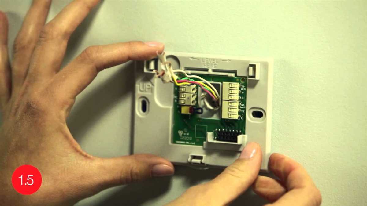
Identifying and labeling the wires on your existing thermostat
Before installing a new Honeywell WiFi thermostat, it is important to correctly identify and label the wires on your existing thermostat. This will ensure that you connect the wires correctly to the new thermostat and that it functions properly.
Start by turning off the power to your heating and cooling system at the circuit breaker. This will prevent any accidents while handling the wires.
Next, remove the cover of your existing thermostat to expose the wiring terminals. You will typically find a series of labeled terminals, such as R, C, Y, G, W, and O. Each terminal is connected to a specific wire from your HVAC system.
Here is a guide to help you identify and label the wires:
- R (Red): This wire is usually connected to the power supply for both heating and cooling systems.
- C (Common): This wire provides power to the thermostat and is not always present.
- Y (Yellow): This wire controls the cooling system and is connected to the compressor.
- G (Green): This wire controls the fan and is connected to the blower motor.
- W (White): This wire controls the heating system and is connected to the furnace.
- O (Orange): This wire controls the reversing valve in heat pump systems and is not always present.
Once you have identified the wires, use adhesive labels or a marker to label each wire at the thermostat terminals. This will make it easier to connect the wires to the corresponding terminals on the new Honeywell WiFi thermostat.
It is also a good idea to take a photo or make a diagram of the wiring before disconnecting the wires. This will serve as a reference in case you encounter any difficulties during the installation process.
By correctly identifying and labeling the wires on your existing thermostat, you can ensure a smooth installation of your new Honeywell WiFi thermostat and enjoy its advanced features and energy-saving capabilities.
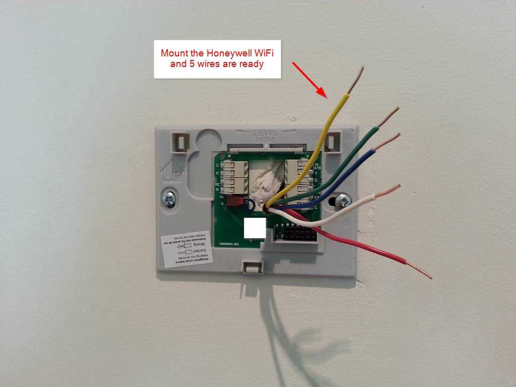
Connecting the wires to your Honeywell Wi-Fi thermostat
When installing a Honeywell Wi-Fi thermostat, one of the crucial steps is to properly connect the wires from your heating and cooling system to the thermostat. This ensures that the thermostat can effectively control the temperature in your home and communicate with your HVAC system.
The specific wiring diagram for your Honeywell Wi-Fi thermostat may vary depending on the model and the type of HVAC system you have. However, there are some general guidelines to follow when connecting the wires:
- Turn off the power: Before attempting to connect any wires, make sure to turn off the power to your HVAC system at the circuit breaker.
- Identify the wires: Each wire from your HVAC system is typically labeled with a letter or a color-coded sticker. Refer to the wiring diagram provided with your thermostat to determine the correct connections.
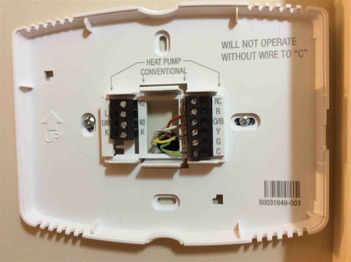
- Match the wires: Connect each wire from your HVAC system to the corresponding terminal on the thermostat. For example, the R wire should be connected to the R terminal, the C wire to the C terminal, and so on. Make sure to tighten the screws on the terminals to secure the connections.
- Extra wire: In some cases, you may have an extra wire that is not connected to any terminal. This wire is often referred to as the “C” wire or common wire. It is used to provide a continuous source of power to the thermostat. If your thermostat requires a C wire and you don’t have one, you may need to consult a professional to install a C wire or use alternative solutions such as a power adapter or a thermostat that doesn’t require a C wire.
- Test the connections: Once all the wires are connected, double-check the connections to ensure they are secure. Then, turn on the power to your HVAC system and test the thermostat to see if it is functioning properly. Follow the instructions in the thermostat’s user manual to set up the Wi-Fi connection and customize the thermostat settings.
By carefully connecting the wires to your Honeywell Wi-Fi thermostat, you can enjoy the convenience of controlling your home’s temperature from anywhere with an internet connection.
Configuring your Honeywell Wi-Fi thermostat using the wiring diagram
If you have a Honeywell Wi-Fi thermostat and want to configure it properly, the first step is to refer to the wiring diagram provided. The wiring diagram shows the various terminals on the thermostat and how they should be connected to the corresponding wires from your heating and cooling system. It is important to follow the wiring diagram precisely to ensure proper functionality of your thermostat.
Start by identifying the various wires coming from your heating and cooling system. Commonly, these wires are color-coded for easy identification. The wiring diagram will indicate which terminals on the thermostat should be connected to each wire. For example, the “R” terminal is usually for the power supply wire, the “W” terminal is for the heat wire, the “Y” terminal is for the cooling wire, and so on.
Once you have identified the appropriate terminals on your thermostat and the corresponding wires, carefully connect each wire to its designated terminal. Ensure that the connections are secure and tight to avoid any loose connections or potential issues. If you are unsure about the specific terminals or wiring configuration, consult the user manual or contact Honeywell support for assistance.
After all the wiring connections have been made, power on your heating and cooling system. Your Honeywell Wi-Fi thermostat should now be ready to configure. Follow the instructions in the user manual to connect the thermostat to your home’s Wi-Fi network and set up any desired temperature schedules or settings.
By properly configuring your Honeywell Wi-Fi thermostat using the wiring diagram, you can ensure that your heating and cooling system operates efficiently and effectively, providing comfort and energy savings for your home.
Testing and Troubleshooting the Thermostat Installation
After completing the installation of your Honeywell WiFi thermostat, it is important to test and troubleshoot the system to ensure it is functioning properly. Here are some steps you can follow to test and troubleshoot your thermostat installation:
- Check power supply: Make sure the thermostat is receiving power. Check the circuit breaker to ensure it is not tripped. If the thermostat is battery-powered, check and replace the batteries if necessary.
- Verify thermostat settings: Double-check that the thermostat is set to the correct mode (heating or cooling) and that the temperature settings are appropriate for your needs.
- Test the HVAC system: Turn on your heating or cooling system and verify that it responds accordingly. Check if the system is heating or cooling as expected.
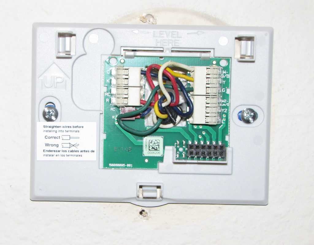
- Check for wiring issues: Inspect the thermostat wiring for any loose or disconnected connections. Ensure that the wires are properly connected to their respective terminals on both the thermostat and the HVAC system.
- Verify WiFi connectivity: If your thermostat is WiFi-enabled, verify that it is connected to your home’s WiFi network. Check the WiFi settings and make sure the thermostat is connected to the correct network.
- Test remote access: If you plan to control your thermostat remotely using a smartphone or computer, test the remote access functionality to ensure it is working properly. Install the corresponding mobile app or access the thermostat’s web interface and check if you can control the thermostat remotely.
- Monitor temperature accuracy: Use a separate thermometer to monitor the temperature in the room. Compare the reading on your thermostat with the separate thermometer to verify the accuracy of the thermostat’s temperature readings.
- Refer to the user manual: If you encounter any issues during testing or troubleshooting, consult the user manual provided with your Honeywell WiFi thermostat. The manual will contain specific troubleshooting steps and contact information for technical support.
By following these steps and troubleshooting any issues that arise, you can ensure that your Honeywell WiFi thermostat is installed correctly and functioning properly. If you are still experiencing problems, don’t hesitate to reach out to Honeywell’s customer support for further assistance.