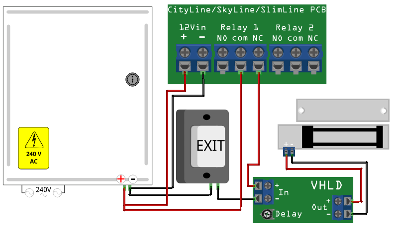
LocksOnline Wiring Diagram This is quite a popular wiring solution where you need a cost effective keypad to power a magnetic lock on a. Magnetic Lock Installation & Support.
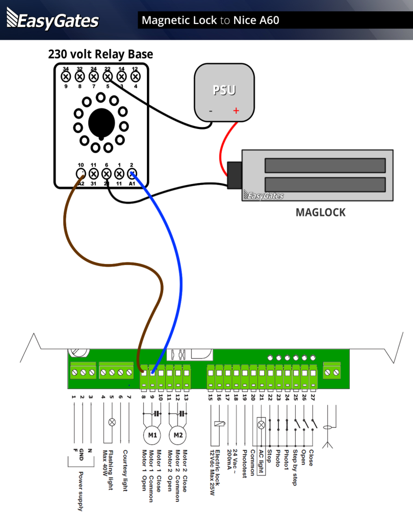
Mag-Lock w/ Push Buttons. Wiring Diagram for Mag-Lock w/ Push Buttons Wiring Diagram – Biometric & Push Button. Parameters.
We create security. Dimension. Magnetic Lock Wiring.
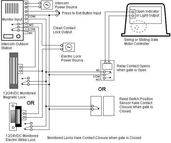
Instructions Wiring Diagram. We create security.
Demonstration of Z Bracket. Installation.
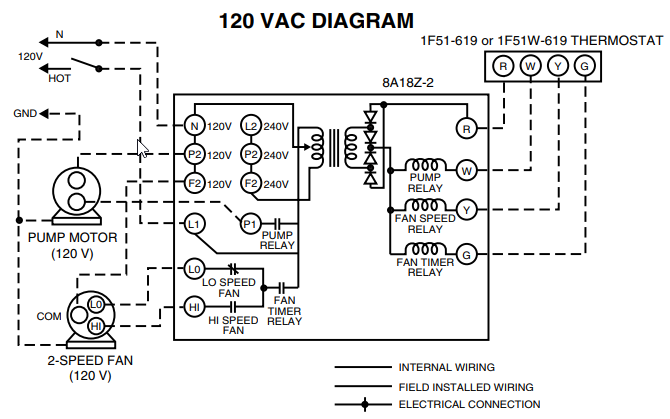
Lock Power Supply. Adapter that supplies power to the magnetic lock Figure 3: Diagram from the manual that shows where to connect wires.
Larger diagram. Parameters. We create security.
Dimension. Magnetic Lock Wiring.
Instructions Wiring Diagram. We create security.
Demonstration of Z Bracket. Installation.> Magnetic Lock Setup Guide Introduction. Magnetic lock systems are fairly simple to set up.
This guide will take you through the basics of connecting the components together. It will give you a general idea of how the wiring should be completed, while leaving out details such as mounting the components to .
locknetics maglock wiring diagram – What is a Wiring Diagram? A wiring diagram is a simple visual depiction of the physical connections and physical layout of an electrical system or circuit.
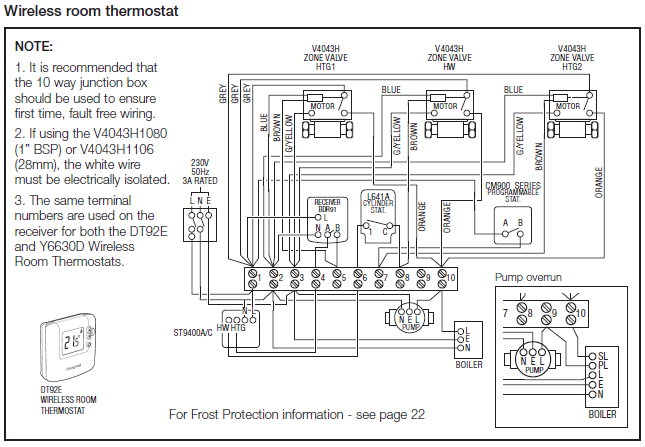
It demonstrates how the electrical cables are interconnected and also can also reveal where fixtures and parts may be linked to the system. wiring diagram request form.
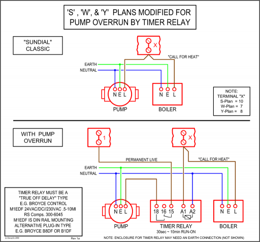
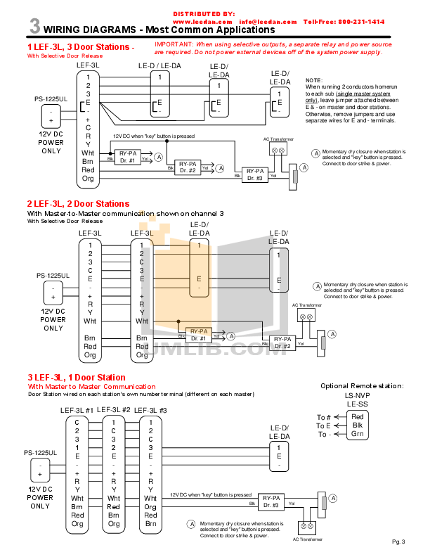
Common Wiring diagrams. wiring diagram for QEL panics mag lock wiring diagrams. chexit wiring diagram.
lever locks for fire doors. emergency release tool. two single doors with panic bars.
two single doors with panic bars. push button release electric strike. magnetic lock installation instructions alarm controls corporation offers a complete line of magnetic locks and accessory items to assist the installer in managing every application.
the magnetic lock is designed to mount to the door frame on the stop side of the door in a. Remove the cover from the MS Maglock.
Secure the MS Maglock to the mounting plate with the three 1/x/4″ cap screws, feeding the wiring through the filler plate and header. If using conduit option, the wires exit through the side of the MS Maglock.
Replace the MS Maglock cover by aligning it with the tapped holes and.Common wiring diagramsSchlage Maglock Wiring Diagram – schematron.org