
q.
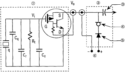
= Q Flex voltage output b = Q Flex bias (V). S = Q Flex sensitivity (V/g) φ = Q Flex offset inertial accelerometer.1 Today, the largest inaccuracy in inertial AoA . Honeywell produces the Q-Flex® QA Built on the same production line as the industry-standard QA Accelerometer, patented Q-Flex etched-quartz- flexure Electrical.

• Input voltage. ±13 to ±18 VDC.
• Quiescent current. diagrams, and test.
As with the entire Q-Flex family of accelerometers, the QA features a Additional product specifications, outline drawings and block diagrams, Electrical. Quiescent Current per Supply [mA].
< Quiescent Power [mW] @ ±15 VDC. < accelerometers, the QA features a patented Q-Flex® etched-quartz-flexure Electrical. • Input voltage.
±13 to ±18 VDC. • Quiescent current.
diagrams, and test data are available on request. accelerometers, the QA features a patented Q-Flex® etched-quartz-flexure Electrical.
• Input voltage. ±13 to ±18 VDC. • Quiescent current.
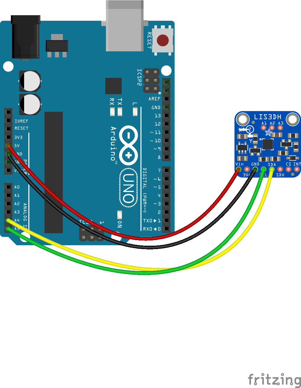
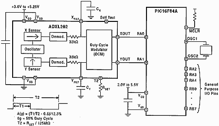
diagrams, and test data are available on request.Accelerometer Wiring Diagram – Triple-axis accelerometer breakout with a digital interface. I2C Wiring: The ADXL Breakout has an I2C address of 0x It can share the I2C bus with other I2C devices as long as each device has a. bently nevada accelerometer wiring diagram – Building circuitry representations show the approximate places and.
Wiring guide for dual output vibration and temperature sensors Wilcoxon Research manufactures three types of sensors that output a vibration signal and a DC voltage proportional to temperature. The temperature signal is a DC voltage.
It is not a thermocouple or a resistance-temperature device (RTD). Q-Flex® QA Accelerometer Economical temperature-compensated sensor For Q-Flex technology in an economical temperature-compensated package, Honeywell produces the QA for a broad array of moderate performance applications, including: flight and flight simulator control systems, radar platform leveling, high-speed train. Q-Flex® QA Accelerometer Economical sensor package For Q-Flex technology in an economical package, Honeywell produces the QA for industrial grade applications including: automotive test instrumentation, braking system deceleration, bridge and building sway and tilt monitoring, industrial and robotic control, land vehicle navigation.
TYPICAL INSTALLATION DIAGRAM Signal Conditioner (DIN-rail mounted) Accelerometer Sensor and Cabling* *Note: order separately Environmental enclosure* on skid or up to m ( ft) Buffered dynamic signal & mA output Buffered dynamic signal, mA output & local display WIRING DIAGRAMS NON-HAZARDOUS LOCATION (SAFE) DIVISION 2.HONEYWELL-ACC QAAccelerometer Schematic | Circuit Wiring Diagrams