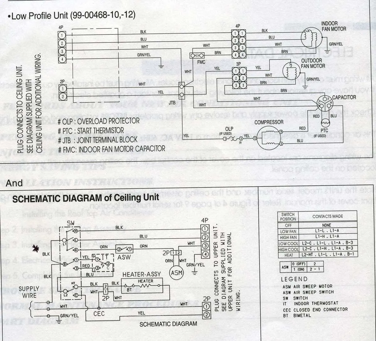
Begin by verifying the model number and matching it with the official control schematic located on the unit’s panel. This blueprint varies across models, particularly between single-stage and multi-stage systems. Misidentifying terminals can cause control board damage or compressor failure.
Low-voltage conductors typically involve terminals marked R, C, Y, O/B, G, and W. The red wire supplies 24V power from the control transformer to the thermostat. Y activates the compressor contactor; G controls the blower relay. O or B adjusts the reversing valve depending on whether the unit is configured for cool or warm mode by default.
High-voltage paths demand attention to the disconnect switch and breaker rating. Confirm that L1 and L2 from the service panel feed directly into the contactor. Ensure a solid ground connection, bonded to the cabinet and verified with a multimeter.
In dual-fuel configurations, verify that the auxiliary heat stage isn’t enabled when the outdoor sensor detects temperatures above the balance point. Jumper settings on the control board may need adjustment depending on thermostat compatibility and staging logic.
Before energizing the unit, inspect every terminal screw for torque, confirm capacitor ratings, and ensure that the crankcase heater (if present) is powered continuously. Label every conductor during disassembly to reduce confusion during reassembly.
Electrical Layout: Air Conditioning Unit by Rheem
Begin by switching off power at the breaker panel to avoid electrical hazards. Remove the access panel on the outdoor condenser to reach the terminal block and control board.
Connect the 24V thermostat wires to the designated Y, O/B, R, and C terminals. Ensure the Y line runs to the contactor coil, and the O/B line correctly controls the reversing valve, depending on the system’s mode default (cool or heat).
The compressor and fan motor connections are typically marked on the schematic inside the access cover. Follow the color codes strictly: black and red are usually high voltage lines, while yellow, blue, and brown handle control signals and capacitor links.
Capacitor terminals must be labeled correctly–HERM (compressor), FAN, and C (common). Miswiring these points can cause component failure. Match the microfarad rating exactly when replacing the dual capacitor.
Low-voltage lines from the air handler or furnace should terminate at the air handler board and connect cleanly to the outdoor section. Seal all wire entries with grommets to protect against moisture and abrasion.
Always refer to the factory schematic inside the unit’s panel cover, which reflects the exact internal configuration. Recheck all screw terminals for tightness before restoring power.
How to Identify and Label Terminals on a Control Board
Begin by disconnecting all power to the unit to prevent short circuits or injury. Use a flashlight and multimeter to locate and verify terminal functions.
R, C, Y, O, W, and G are the most common low-voltage contacts. R (usually red) supplies 24V AC power; C (common) completes the circuit. Y activates the compressor contactor; O switches the reversing valve; W controls the electric strips, and G engages the blower relay.
Check the printed board markings. Factory labels are often next to screw terminals or quick connects. If not labeled, trace color-coded wires from the thermostat and condenser relays to determine function. Compare wire colors with manufacturer documentation if available.
Use adhesive markers or a label maker to tag each wire before disconnecting anything. Keep the labeling consistent with standard HVAC terminal codes.
Take a photo of the board before altering connections. This serves as a reference in case labels fall off or fade during repairs.
Thermostat Connections to Outdoor Unit
Connect the thermostat terminals according to the following signal assignments to ensure proper operation of the HVAC system:
- R (Red): 24V AC power from the control transformer. Connect to R on the control board.
- C (Common): Provides return path for 24V power. Connect to C terminal on the air handler or condenser.
- Y (Yellow): Engages the compressor contactor. Route this wire to the Y terminal on the contactor coil.
- O (Orange): Controls the reversing valve. This must be energized in cooling mode. Link to O terminal on the solenoid valve.
- G (Green): Activates the indoor blower relay. Connect to G on the fan relay or air handler board.
- Aux/E (White): Engages auxiliary or emergency heat strips. Link this to W1 or E depending on configuration.
Use an 18/8 thermostat cable to support all standard connections. Always verify voltage presence and proper grounding before powering the system.
Troubleshooting Common Electrical Connection Issues in Rheem HVAC Systems
Begin by verifying all terminal screws are securely tightened to prevent intermittent faults or complete power loss. Loose contacts often cause system failures or erratic operation.
Check the continuity of control circuits using a multimeter. Open or shorted control lines can interrupt signal transmission between the thermostat and compressor unit.
Inspect the capacitor terminals for corrosion or burn marks, which indicate potential failure. Replace capacitors showing visible damage or readings outside manufacturer specifications.
Confirm that the contactor coil receives proper voltage during system call. Absence of voltage suggests problems in the control transformer or wiring harness leading to the relay.
Evaluate sensor leads for cuts or insulation wear. Damaged sensor connections may cause inaccurate temperature readings, resulting in incorrect cycling.
Verify proper grounding of the entire assembly to avoid electrical noise interference and potential safety hazards. Use a grounding tester if necessary.
Ensure the reversing valve control wire is connected correctly and is not damaged. Faults here can prevent mode switching between cooling and heating functions.
Examine the low-voltage terminal block for loose or crossed wires, which can trigger fault codes or system lockouts. Use the manufacturer’s service manual to confirm correct pin assignments.