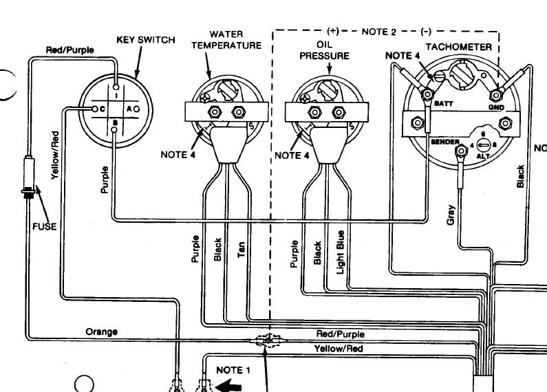
On the back on the left are 2 male spade terminals. Thread: vdo engine synchronizer wiring diagram??
signal to electronic tachometers. either via gasoline engine ignition pulse, or diesel engine alternator pulse.
IS, D, Depth Sounder – Dual Air/Water Temperature, Owner’s Manual 2 inch Discrete, Installation. IS, D, Fuel Flow Manager ( mb), Owner’s Manual IS, C, Serial Bus Gauges – CorrectCraft – PleasureCraft GM engines ( mb), Owner’s Manual. IS, A IS, B, Synchronizer – Suzuki , Installation. The Faria Marine Instrument Bracket Mount Dual Engine.
Synchronizer is case of outboard engines). Like a tachometer, the Synchronizer counts “pulses” from.
Page of links to the technical section for Faria gauges. ISe – Commander Tachometer-Engine Running Only Hourmeter – Owners Manual (mb).
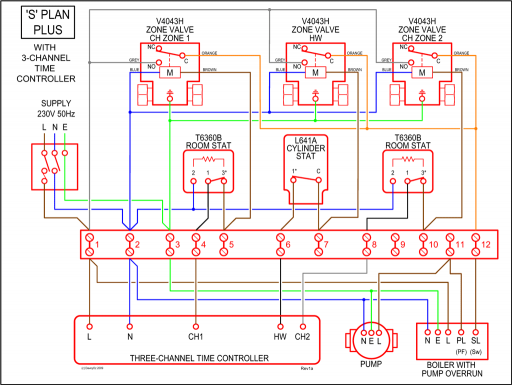
The two most critical parts of the EEC system installation are the following: Component This information is used by the System during engine synchronization. any gasoline engine, a mechanical tachometer adapter will have to be used.3” Electric Tachometers / 3” Electric Tach/Hourmeters / to instructions or the diagram at right. The wire connection from the Engine Synchronizer 1.
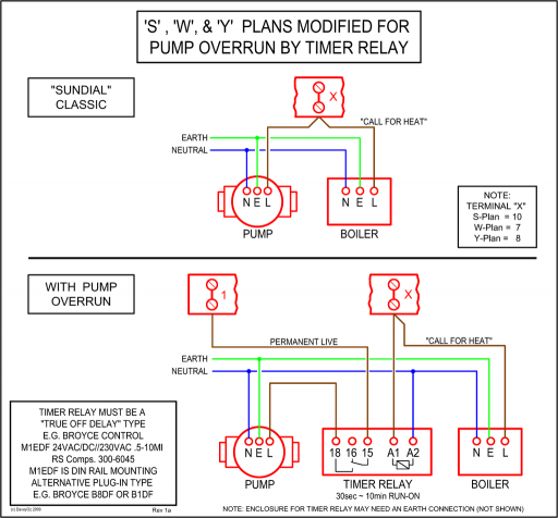
Recheck all wire connections to be certain they are clean and tight. Be sure the two plugs are.
Plan1 Capability List D B B B B NOTE 2: Tachometers with two or three buttons use an advanced microcontroller circuit to measure engine RPM for increased accuracy and zero pointer flutter at low RPM. When used on , 1, or pulse per rev ignitions, a brief pause in pointer movement may be observed as RPM is rapidly decreased.
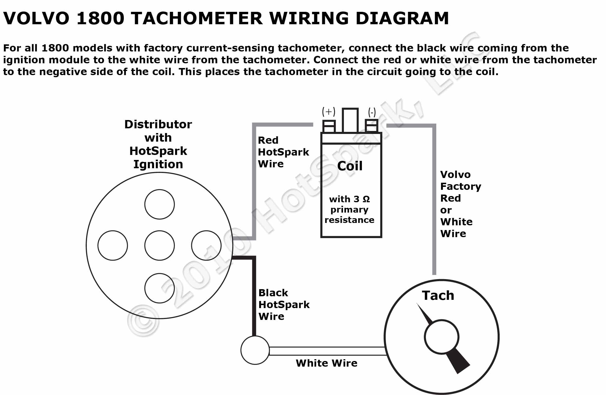
2. Start the engine and determine the actual engine RPM using a reference tachometer (optical, non-contact tachometer recommended). 3.
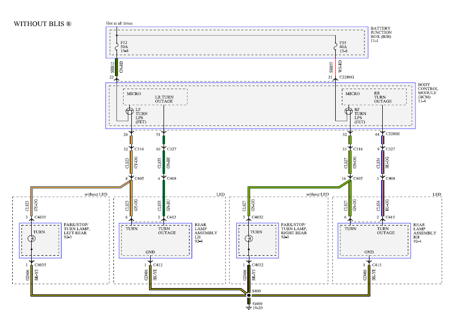
Set the DIP Switches, as a course calibration, so that the tach indicates the closest to actual engine RPM. TIP: A small screwdriver or .
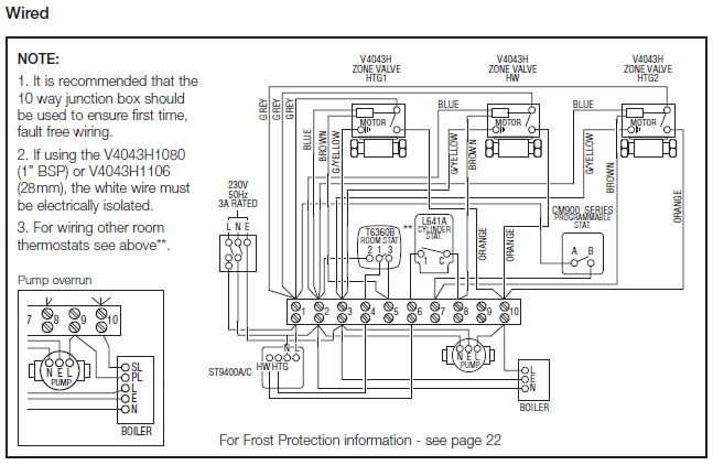
Sep 07, · To test the gauge connect the black wire to the white wire at the tachometer. The bars should all illuminate indicating a full fuel tank. Disconnect the black wire and the bars should disappear except for the bottom bar which will flash.
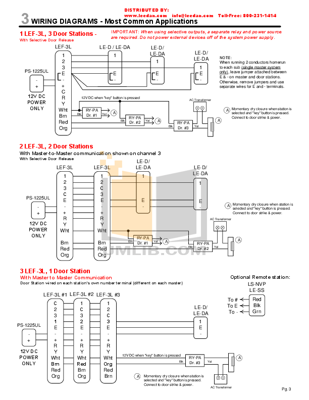
If the tachometer indicates good then you have a wiring problem or a sender problem.Marine Engine Synchronizer – Glendinning ControlsWiring Diagram (Yamaha Gauges) – Yamaha Outboard Parts Forum