Use a dummy load (50 ohm for and ohm for balun) and connect it to the output.
balun wiring diagram. Connect your transceiver. Use a dummy load (50 ohm for and ohm for balun) and connect it to the output.
balun wiring diagram. Connect your transceiver.
This article presents a project to construct a (four to one) current balun in schematic) on each wire-end once seperated into two wire-pairs with eight ends total. .
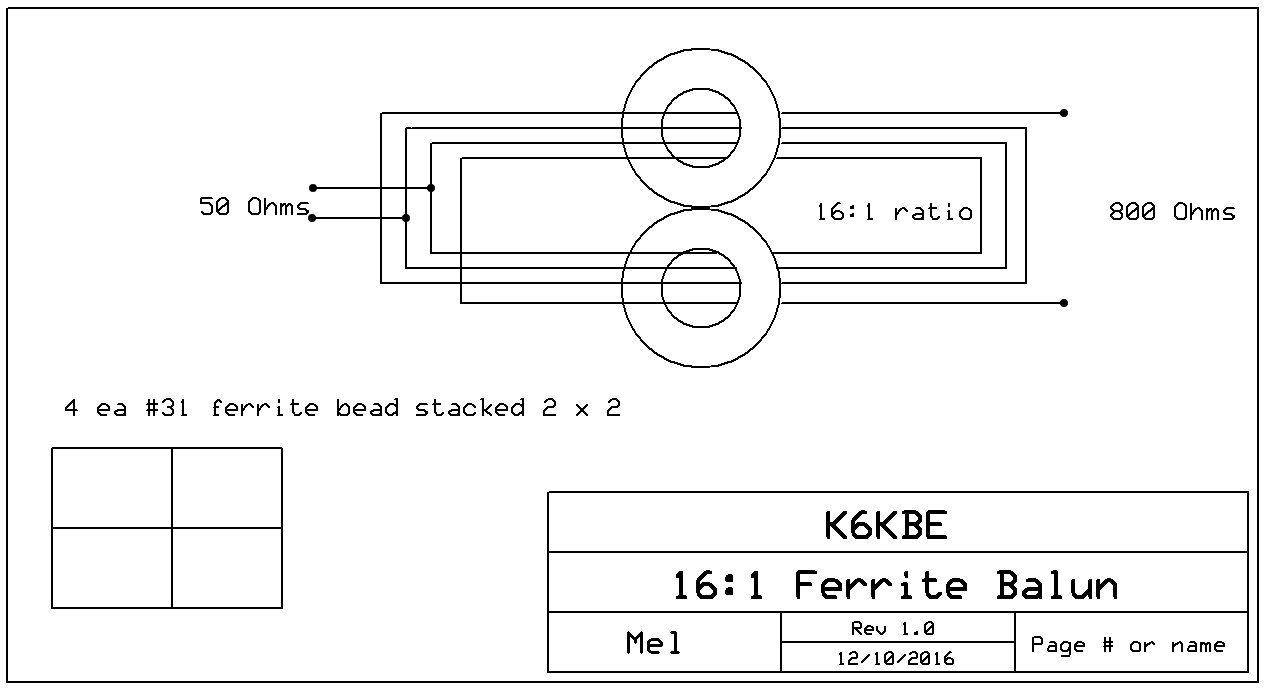
I am confident that this more aesthetic than practical at HF wavelengths. Use a dummy load (50 ohm for and ohm for balun) and connect it to the output.

balun wiring diagram. Connect your transceiver. Baluns (and UnUns) and not complicated devices once you know the basics.

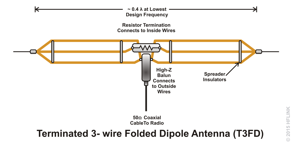
It’ ll easily take w at HF frequencies whilst is rated at w (at 10MHz). coaxial cable over a large ferrite core – see the image below for a wiring layout.These are for a 50 Ohm load.
The core is, according to Balun Designs, custom low-loss. I take it this means a manganese zinc material.
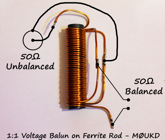
The Fair-Rite 61 material you mention is a manganese zinc ferrite. It sounds as if you are talking about Fair-Rite part number , which has an A_L of (+/- ) nH per squared turn. Heres a neat 50 ohm balun for use on HF horizontal wire dipoles.
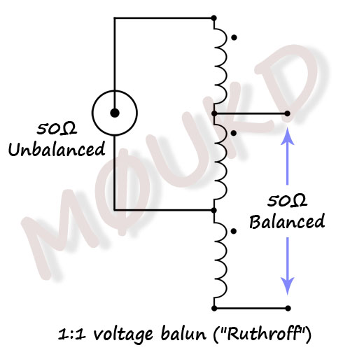
It uses an AM radio ferrite rod, with 3×14 turns of wire. turns should be good for MHz.

I used 18SWG enammeled copper wire. It all fits in a small project box. Great for setting up portable.
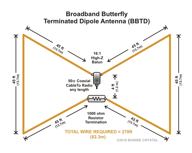
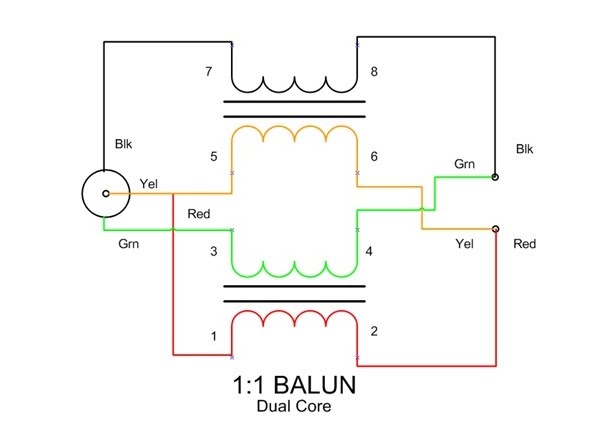
On the Sevick unun, input and output shared a common ground (“1” in your diagram; “2” would be the ohm coax center conductor and “8” is the other ohm terminal). For a balanced output, I would put the ohm feed either between 3 and 4 or 5 and 6. reducing or controlling common-mode current.
Current baluns are the balun of choice in all but very specialized situations, because they work better than voltage baluns in most real-world systems. In the case of a ratio current balun, core flux density or “magnetizing stress” on the balun core is independent of load impedance or load mismatch.
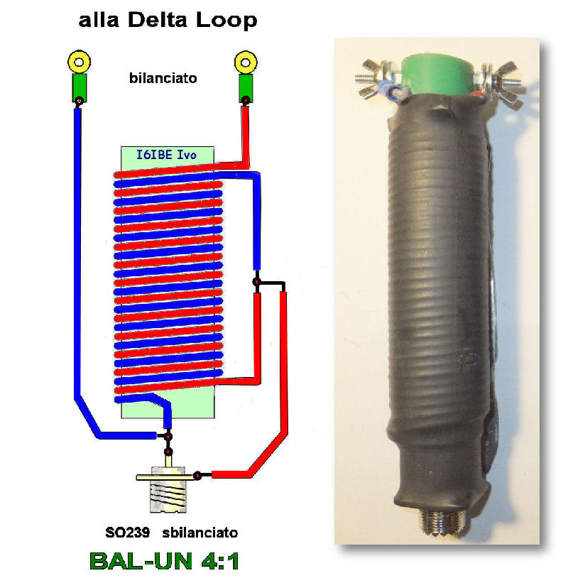
Cctv Balun Wiring Diagram On this website we recommend many designs about Cctv Balun Wiring Diagram that we have collected from various sites of Wiring Diagram Collection, and of course what we recommend is the most excellent of design for Cctv Balun Wiring Diagram.BUILD AN AIR WOUND CHOKE BALUN FOR HF – THE UGLY BALUN!Balun – Wikipedia