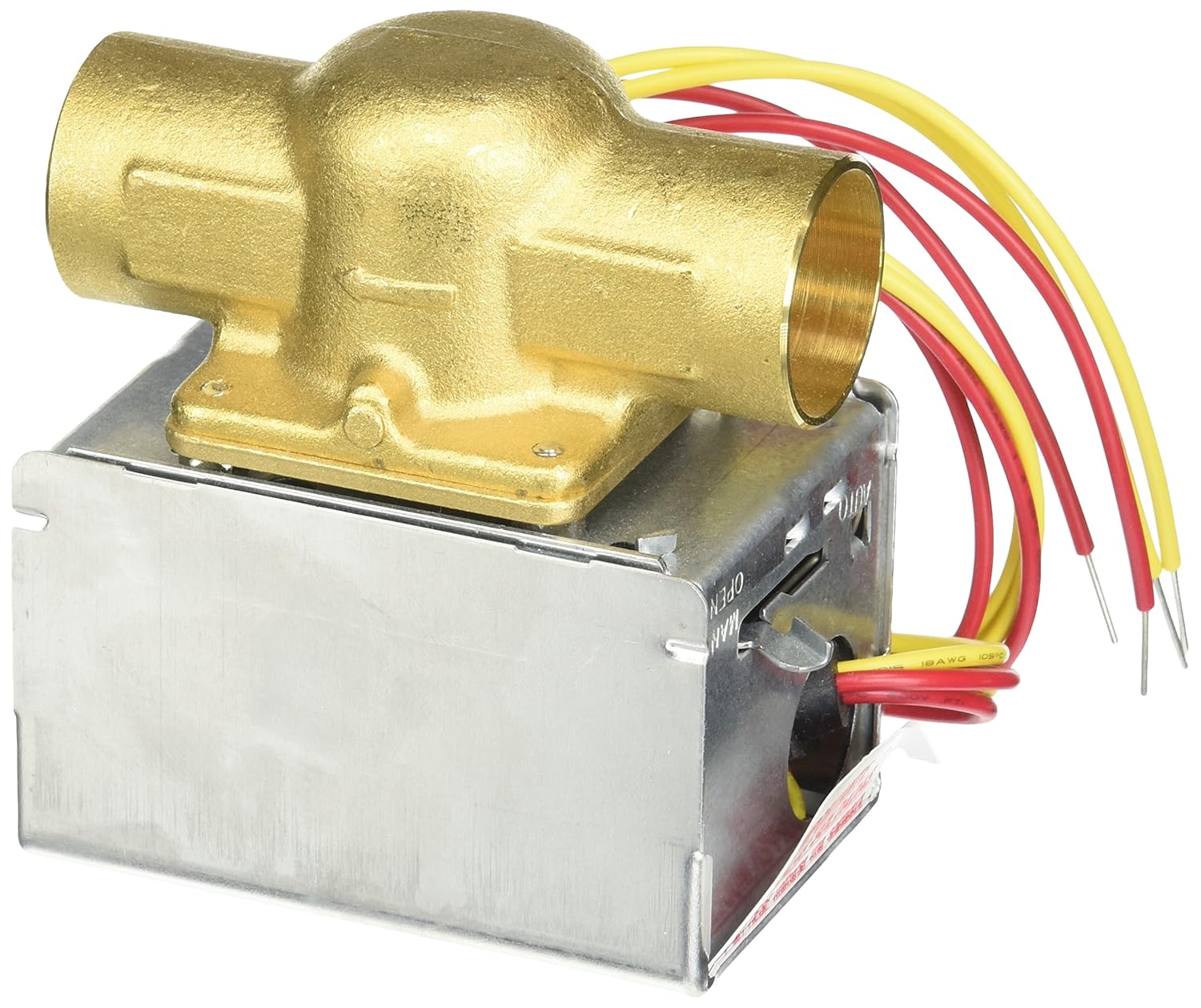
The old owner have installed 4 Honeywell VE zone.
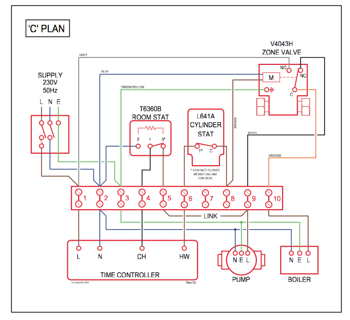
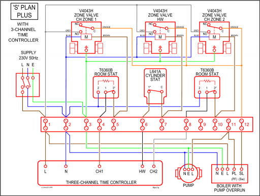
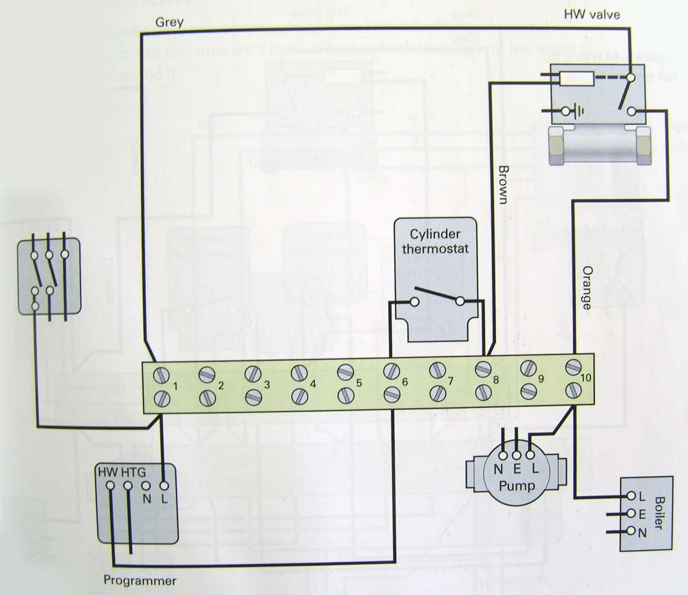
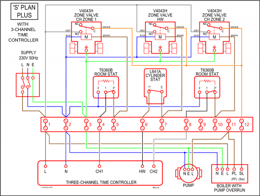
I have followed the wiring diagram and when I turn the thermosat on I can see. Schematic at above-left: wiring hookups for a mixed-brand zone valve installation : Honeywell & White Rogers. Click to enlarge any image or schematic.
The most professional way to wire a Honeywell VE Zone Valve using flex conduit by jerry. schematron.org Schematic at above-left: wiring hookups for a mixed-brand zone valve installation : Honeywell & White Rogers. Click to enlarge any image or schematic.
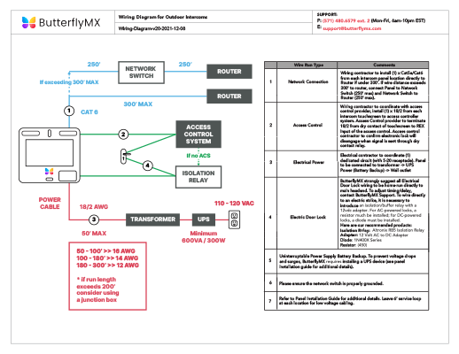
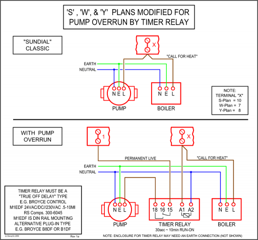
Honeywell A Mid Position Motorised Valve. Installation-Guide and Spare Parts. Find wiring diagram for Y Plan central heating system.Feb 26, · How to Wire a Zone Valve.
A zone valve helps control the heat from a thermostat for an area of your home, such as a bedroom or living room. A control box is wired to thermostats in your house and controls the zone valves.
When a zone valve receives an electrical signal from its thermostat, it Views: 67K. Wiring diagram CR2 01 Wiring Diagram (2 wires control) ·RD connect with positive, the BK connect with negative, the valve closed, the actuator automatically power off .
Need help wiring Honeywell zone valves
Feb 05, · One for the Experts – Motorised Valve Wiring. Discussion in ‘Plumbing and Central Heating’ started by Walkbar, 3 Feb Walkbar.
Joined: 3 Feb Messages: 22 Full wiring diagram is on the Honeywell site for their valve – you should be able to work out which thermostat pins are for “call for heat ” etc. Motor to a water or steam globe valve. Q Damper Linkage connects motor to damper.
Includes motor crank arm. Q External Auxiliary Switch controls auxiliary equipment as a function of motor position.
QA Interface Module with selectable voltage ranges ( Vdc, Vdc, and Vdc) adapts motor to M71XX function. 2 Port Motorised Valve Problems Honeywell Wiring Diagrams Zone Sample.
Click here to see other Collection of honeywell zone valve vf wiring diagram.. Find out more honeywell zone valve vf wiring diagram Gallery below.Need help wiring Honeywell zone valves – schematron.org Community Forumsmotorized valve wiring wire control diagram Instructions
