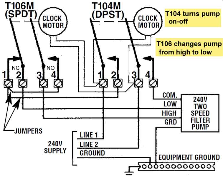
How to wire Intermatic T and T and T timers. Including diagrams for T, T, T timers T / 50Hz timer/ same wiring as T Replacement Comparison Chart – Cross Reference & Ordering Guide * Intermatic, *Tork, *Paragon, Precision Timer TR, CDM, , SPDT Industries; Paragon® is the registered trademark of Paragon Electrical Products.
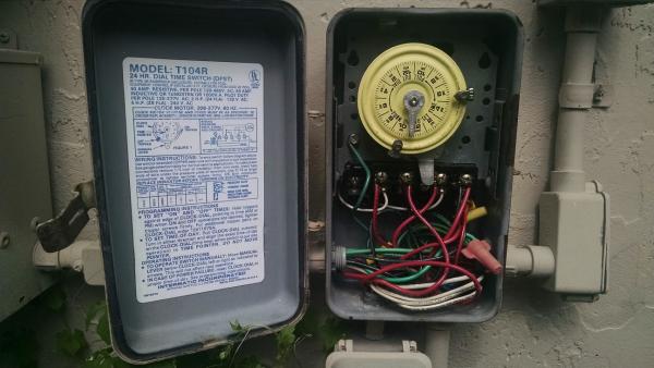
A chart is here: schematron.org~/media/files schematron.org The wires that power the T clock mechanism are white, and they. T & T are Volt timers; T, T & T are Volt timers.
Each timer Manual override lever clicks back and forth with audible sound each time tripper moves on-off lever. Up to 12 Intermatic T series timer, manuals, parts. A T timer is used for V supply voltage.
If you are using V supply voltage, you will need a T timer. The installation steps are the same for either.intermatic pool timer t r dont turns on but do turns off – Intermatic TR Volt amp Timer question. Search Fixya.
Browse Categories Answer Questions Intermatic pool timer t r dont turns on but do turns off. Posted by Anonymous on Jan 22, Want Answer 0.
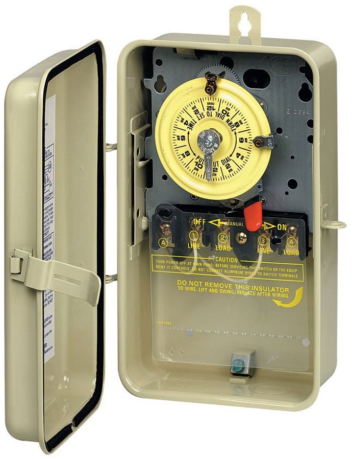
Jun 28, · Installing Intermatic T timer for pool pump I disconnected the old manual switch and installed the T timer switch. I connected the ‘hot wires’ to line 1 and line 3 as instructed and the pump wires to load 2 and load 3 terminals. Intermatic T Timer Wiring Diagram ~ This is images about intermatic t timer wiring diagram posted by Allan L.
Murdock in Intermatic category on Nov 02, You can also find other images like wiring diagram, parts diagram, replacement parts, electrical diagram, repair manuals, engine diagram, engine scheme, wiring harness, fuse box. Nov 06, · The clock on both timers is powered by your main line coming into the T so when you turn off the , the clock on the doesn’t stop.
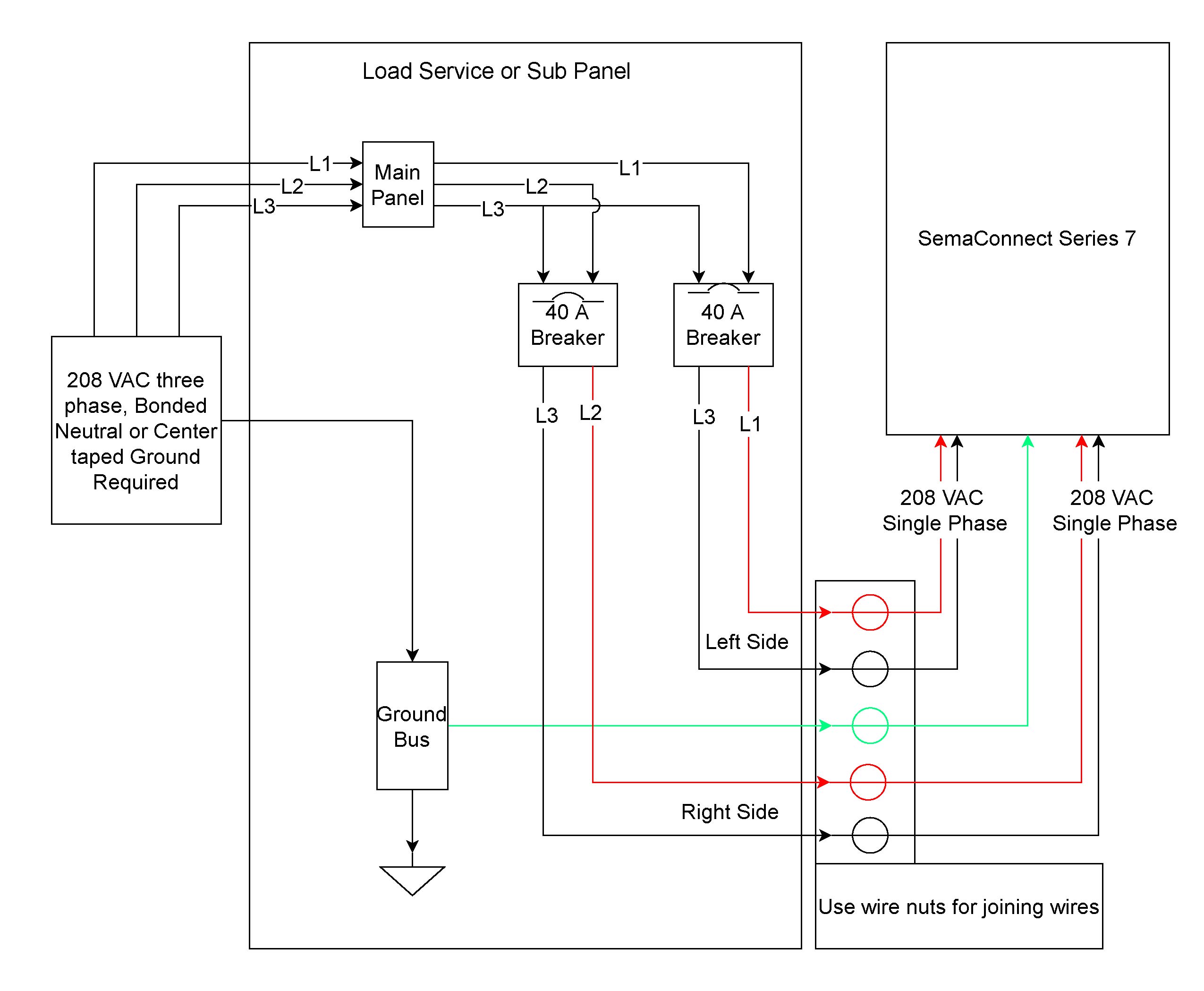
A set of wires is needed to jumper the clock inputs. For others reading this, I prefer to use Intermatic’s PME timer. The white wire is sometimes used as a hot, especially when wiring Intermatic T and T timers.

Also understand that the WHITE neutral wire and the bare (or green) equipment grounding wire are connected together ONLY at the main electric power panel .How to wire T timerHow to wire Intermatic T and T timers – Fixya