Since , Intermatic has been focused on developing and manufacturing offer installation efficiencies that save time and money.
Timer Selection Chart. ETCP.
T 1NO/1NC**. 5.
Model #. Model #.
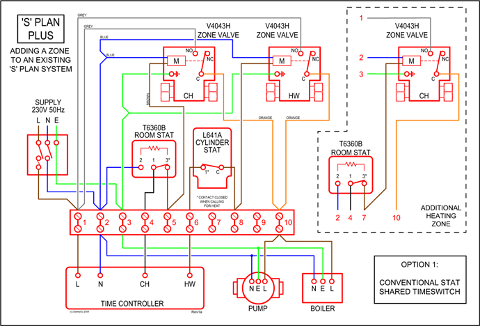
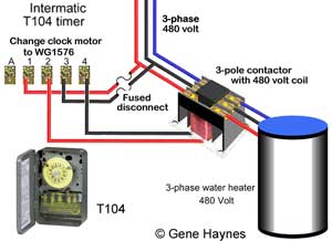
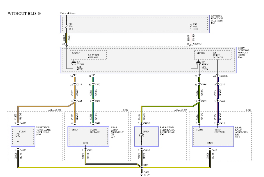
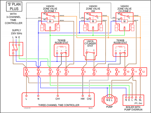
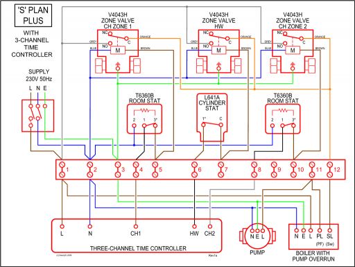
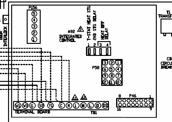
Model #. Model # ON Trippers for TN, PB, TB Series, P, P, P, P Installing an Intermatic T timer is a great way to dramatically reduce run time Your next step is to wire the power from the breaker panel to the pool timer. How to wire Intermatic T and T and T timers.
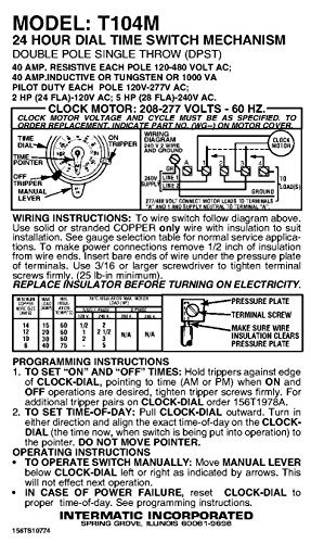
T manual with NO NC terminals Order T timer V 50 Hz T at Amazon. Since , Intermatic has been focused on developing and manufacturing offer installation efficiencies that save time and money.
Timer Selection Chart. ETCP.
T 1NO/1NC**. 5.
Model #. Model #.
Model #. Model # ON Trippers for TN, PB, TB Series, P, P, P, P Buying T timer is probably cheaper and simpler.
schematron.org BJJM7ZS/?tag=waterheaterti · schematron.org schematron.org#T media/files/intermatic/products/instructions/ timers/t%%schematron.org .. Intermatic TM instructions.Jun 28, · Installing Intermatic T timer for pool pump I disconnected the old manual switch and installed the T timer switch.
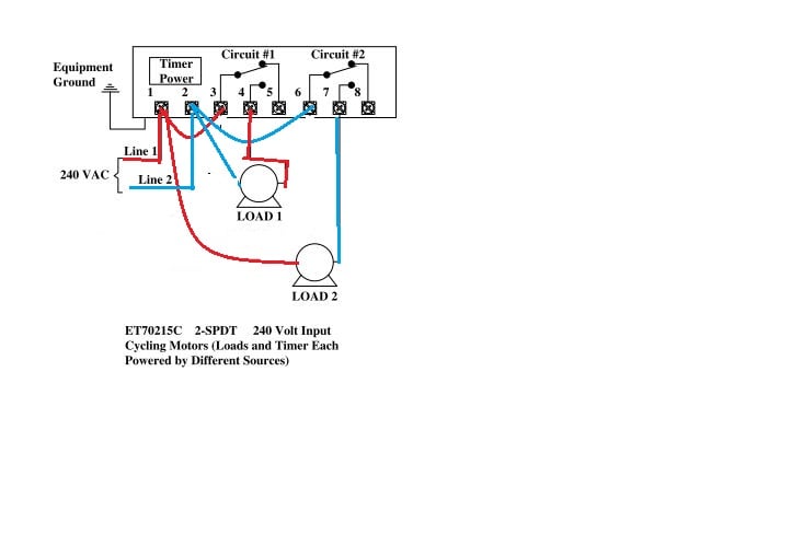
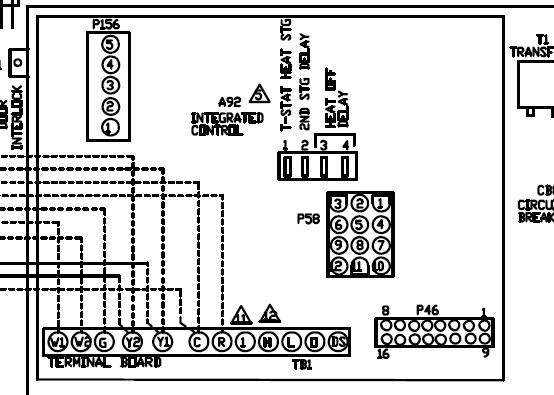
I connected the ‘hot wires’ to line 1 and line 3 as instructed and the pump wires to load 2 and load 3 terminals. Wiring Instructions for an Intermatic Timer. Intermatic Incorporated manufactures timer switches designed for indoor and outdoor use.
Many pool pump motors and water heaters use Intermatic timers to regulate their run times. An Intermatic timer-switch saves electricity when it turns a water heater off at night and when it limits the amount of time. Subscribe to Our Newsletter Sign-up for email alerts for products and software updates, new product releases and information about upcoming events.
The T Series Mechanical Time Switch has proven it can stand the test of time. These dependable time switches can handle electrical loads up to 40 A per .

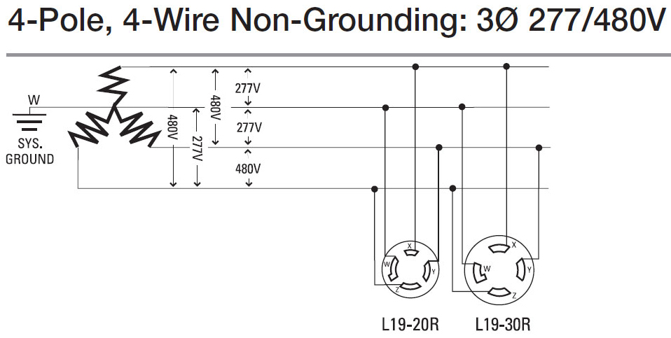
Usually one will find one of the three following scenarios for the incoming supply cables when wiring a T or T Intermatic timer: 1 A volt cable with 3 wires: black, white, and bare. The black is LINE (hot), white is neutral and bare is equipment grounding.SOLVED: How to set up intermatic tm to work with two – FixyaSOLVED: I need instructions for outdoor timer model TM – Fixya
