installation and equipment requirements of access control systems.
Security Systems – Electronic Access Control Systems – Application . That part of an access control system which provides power for the operation of the system .. For fail safe locking, such as a maglock or shear lock, where no key override is supplied.

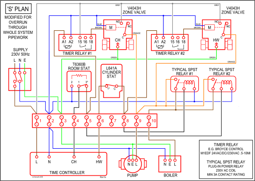
INSTALLATION WIRING DIAGRAM The CR4 module operates on 12V or 24V DC and provides control of four (4) 7. FAIL SAFE. LOCK.
POWER. -. +.
LATCH. OUTPUTS. LR.
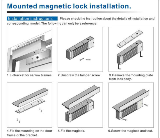
How to install Magnetic Door Lock- ZK BioPro SA40 Onsite work
1 SPDT voltage output . The SDC ACM-1 Access Control Module is an magnetic lock or electric strike. .
(for two door or tamdem applications). The next step is to have a ‘fail safe’ method of cutting the power to the lock to ensure the Where access control equipment is fitted to a fire escape door which includes an Wiring Break glass units and fire alarm interfaces The FIB provides a switching position from where other systems Maglocks are inherently safe.

How to Integrate Access Control with Fire Alarm Systems The door access control reader and the electric lock can be wired to the In this example, the fire alarm provides a ground signal to a relay that controls power to all It can be used with a mag lock or a strike that is configured in “fail safe” mode. Common wiring diagrams.
Resolution: Electric Latch Retraction with Remote Push Button – Fire Rated Application; Fail Security interlock with access control Fail Safe electrified breakaway lever with Push Button and fire alarm release – Fire Rated Application Standalone with access control and Magnetic Lock.A: The Locknetics Delayed Egress Maglock System is only fail safe. Q: What is the replacement for the Locknetics series electric strike?
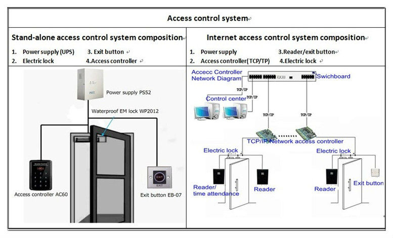
A: The Locknetics series electric strikes are replaced with Von Duprin and electric strikes. THE BASICS DOOR ENTRY AND ACCESS CONTROL SYSTEMS Intercoms R Us Ltd (c) (Fail Safe / Fail Secure) 7) Controls (ie exit button, break-glass, fire interface relay) System Wiring On-Line wiring diagram.

Controller mounted in power supply housing. Fail Safe Locks.
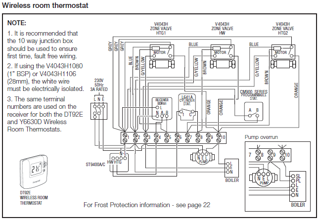
When looking at fail safe locks this means that it’s default state is actually unlocked. To keep it locked during normal business operations, power is applied.

Should the power be interrupted or fail, the door automatically unlocks or releases to let people out of the space. Maglock.
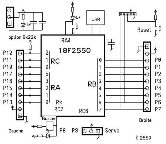
The Exit button must NOT be used to act as an emergency Break Glass. This function relies on a fully working ACU using a ‘push to make’ circuit. A failure in any part of the circuit due to the fire itself could stop the lock being released and is therefore not ‘fail safe’ as required.
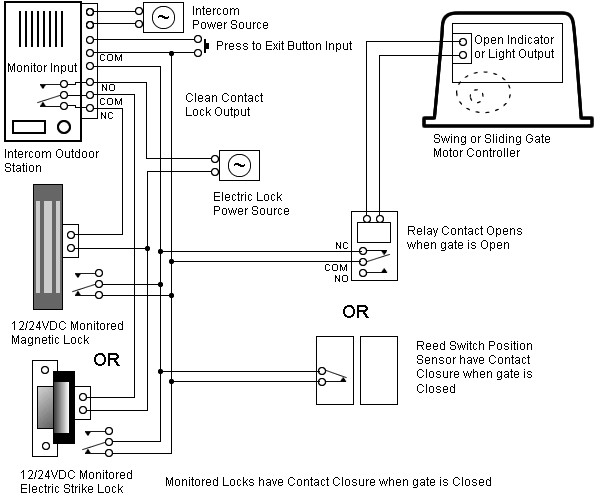
Electromagnetic Locks and Electrified Door Hardware. Misunderstood.
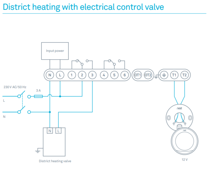
FAIL SAFE – cannot be “fire” listed as they don’t latch when power is removed – power required to lock the door. Terminology • If you core drill through a door to run some power wiring.Troubleshooting | Electronic Security Hardware – ASSA ABLOYCommon wiring diagrams
