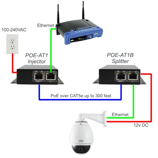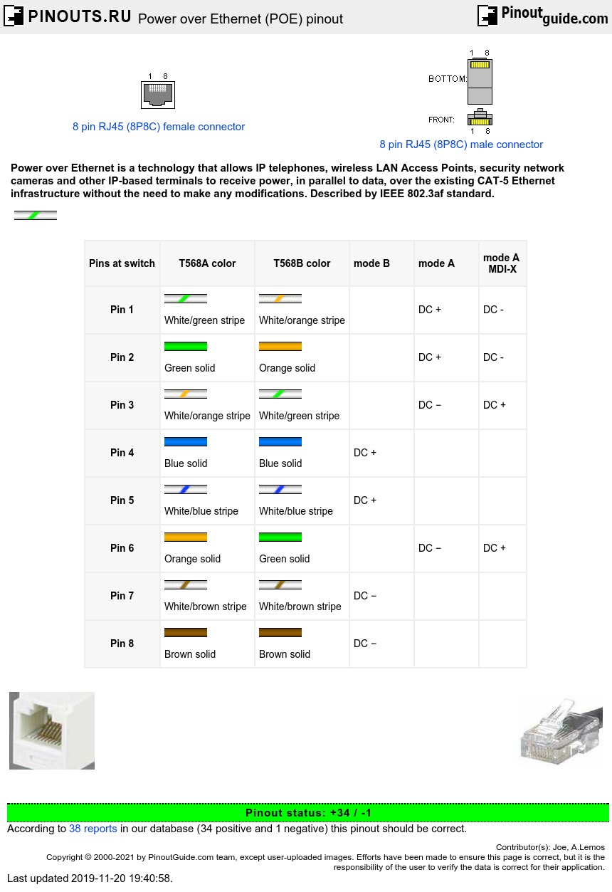
Wiring diagram for a PoE injector (midspan) and an af (at type 1) powered device.
Option A – violet color, option B – yellow color. Wiring diagram for a.
Based on the standards diagram posted in another answer and sourced from Wikipedia, the POE issue with crossover cables comes if the. PoE integrates data and power on the same wires, while keeping the as a PoE power injector, is an additional PoE power source that can be. By using Power over Ethernet power injector, all the installers need is to run a single CAT5 or CAT5E Ethernet cable that carries both power The Injector is typically installed in the wiring closet near the Ethernet hub or switch.

Schematic. Power Over Ethernet (PoE) Adapter: Power over Ethernet or PoE, is the technology used for The connection should be made according with the schematic.PoE begins with a CAT5 or CAT5E or CAT6 (fast Ethernet cable) power voltage Injector, that inserts a DC Voltage onto the cable.
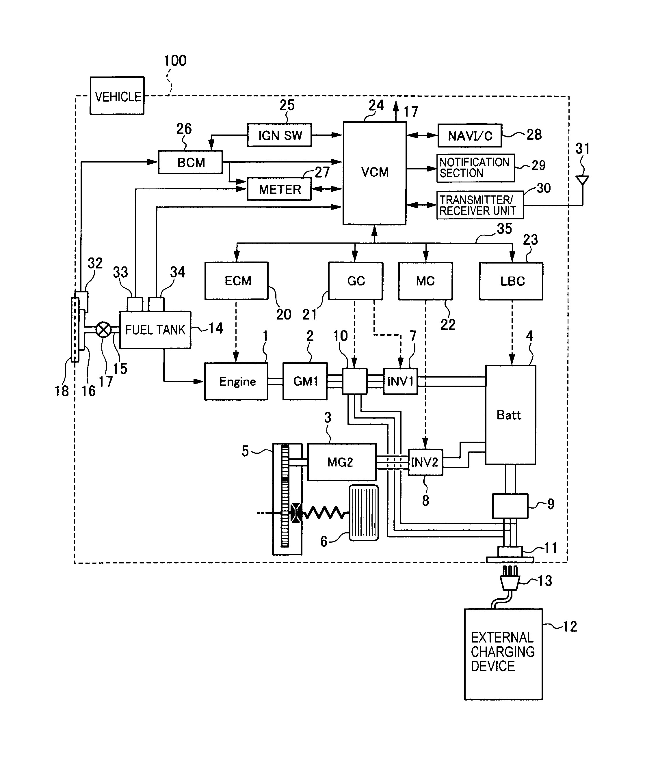
The Injector is typically installed in the wiring . A midspan power supply, also known as a PoE power injector, is an additional PoE power source that can be used in combination with a non-PoE switch.

Standards-based Power over Ethernet is implemented following the specifications in IEEE af A phantom power technique is used to allow the powered pairs to also carry data%(31). With a PoE IP camera injector, you will need to plug the Ethernet cable of the PoE CCTV camera into the injector, connect the injector with your router, and then power the injector.

To avoid this, the best way is to make a PoE adapter, separating the two input signals, via two simple circuits, an injector and a splitter. The injector will feed the network cable with power and this circuit is placed near the origin of the installation, where we have a modem or a . Wiring diagram for a PoE injector (midspan) and an af (at type 1) powered device.
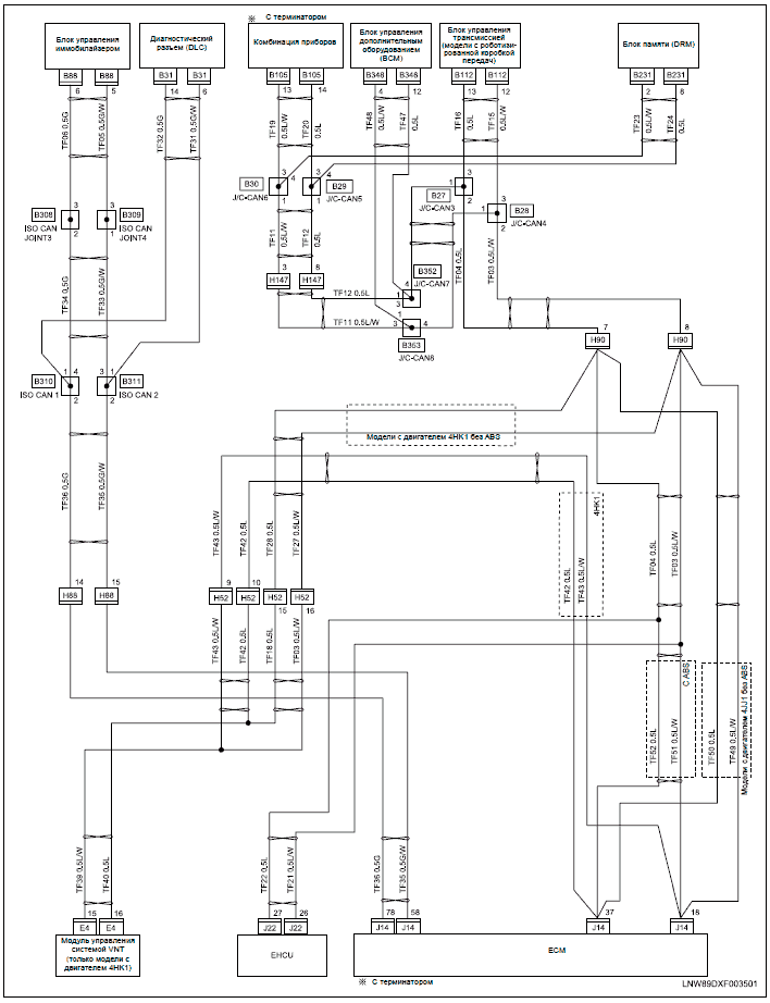
Option A – violet color, option B – yellow color. Wiring diagram for a PoE switch (endspan) and an at type 2 (PoE+) powered device.POE Explained – Understanding and using Power over EthernetPower over Ethernet (POE) pinout diagram @ schematron.org
