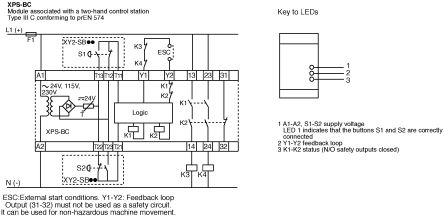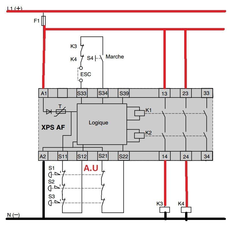
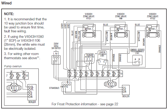
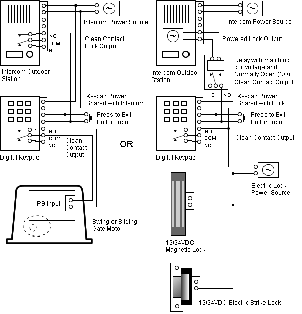
Wiring Diagrams.
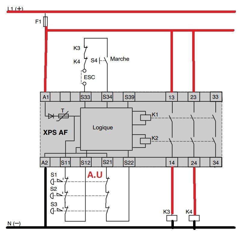
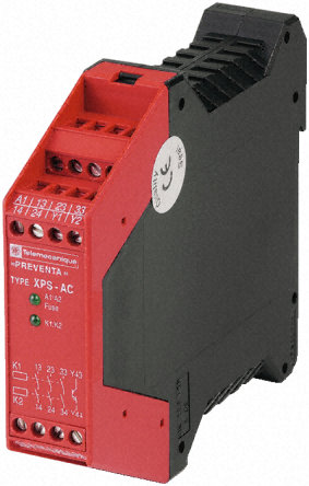
XPSAC module with an ESC: External start conditions. Functional diagram for module XPSAC ..

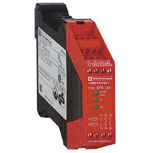
XPSAF XPSAFP. Product.
For the XPSAF, it is the standard wiring diagram to use: in the instruction sheet, you replace the schematron.org mushroom by the XY2C* rope pull switch to get a. Preventa safety modules XPSBA/BCE/BF for electrical monotoring of two-hand control stations. .. A diagram representing the function is given opposite; it must meet the following requirements: ..
XPS AF 4. –.

– e. –. Buy SCHNEIDER ELECTRIC XPSAF online at Newark element Monitoring of a movable guard, emergency stop monitoring 1-channel wiring.
The diagram to the left illustrates the operation of a light curtain. Functions of a non-contact safety ..
connection of safety related output devices, such as contactors, illuminated beacons, sirens, etc. XPSAF XPSAFP.
Product.XPSAF module XPSAF – Emergency stop – 24 V AC DC Main Range of product Preventa Safety automation Product or component type Preventa safety module Safety module name XPSAF Safety module applica-tion For emergency stop and switch monitoring Function of module Monitoring of a movable guard Emergency stop monitoring 1-channel wiring. How to combine the XY2C (schematron.org rope pull s/w) with XPSAF safety relay?

Products. All Products. All Products.
Looking for product documents or software? Go to our Download Center.
Residential and Small Business. Electrical Protection and Control.
Home Automation. Home Security.
Safety Relays Type XPSAV, XPSATE & XPSVNE Catalog Supplement to CT The Start button monitoring function is configurable depending on the wiring. Characteristics: Module type: XPSAV and AVP XPSATE: pppp and ATEppppP Wiring Diagrams: page 6 Dimensions. Text: 2 XPSAF 3 a and c 24 V XPSAFP () DF Removable from module 3 4 XPSAFP 5 Wiring diagrams 6 XPSAF Module XPSAF associated with an, relay modules type XPSAF For Emergency stop and switch monitoring Operating principle Safety modules XPSAF are designed to conform with category 4 of the standard EN/ISO Y33/Y43 EN/2 EN EN/3 EN/2 star delta wiring diagram motor start y wiring diagram STAR DELTA motor starter wiring diagram, variable speed drives XPSVNEP wiring diagram motor start y XPSVNEP star delta starter diagram xps ak VNEP star delta connection LOGIC wiring circuit diagram: Telemecanique LIMIT SWITCH XCK-J.XPSAF – module XPSAF – Emergency stop – 24 V AC DC | Schneider ElectricPreventa XCS – Wiring diagram of the solution 2 XCSDMC* magnetic switches and XPSAF(P) unit
