DESCRIPTION.
YM8MA12MP11A YM8MB12MP11A YM8MC16MP11A ELECTRICAL. 2.
3. CAPACITOR . ELECTRICAL.
2. 3 York Drive.
First, You must accept the Wiring Diagrams Disclaimer at the bottom of this section (by reading, then clicking on the “Accept” button). DESCRIPTION.
YM8MA12MP11A YM8MB12MP11A YM8MC16MP11A ELECTRICAL. 2. 3.
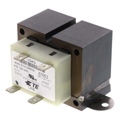
CAPACITOR . ELECTRICAL. 2.
3 York Drive. First, You must accept the Wiring Diagrams Disclaimer at the bottom of this section (by reading, then clicking on the “Accept” button). DESCRIPTION.
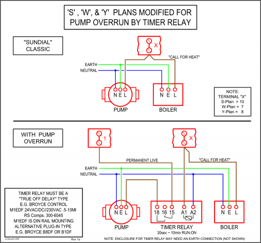
YM8MA12MP11A YM8MB12MP11A YM8MC16MP11A ELECTRICAL. 2.
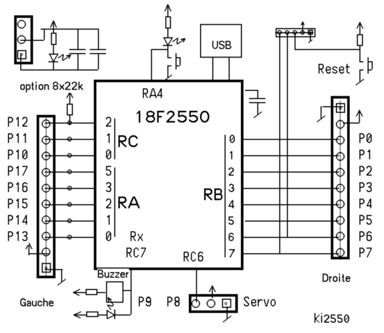
3. CAPACITOR . ELECTRICAL.
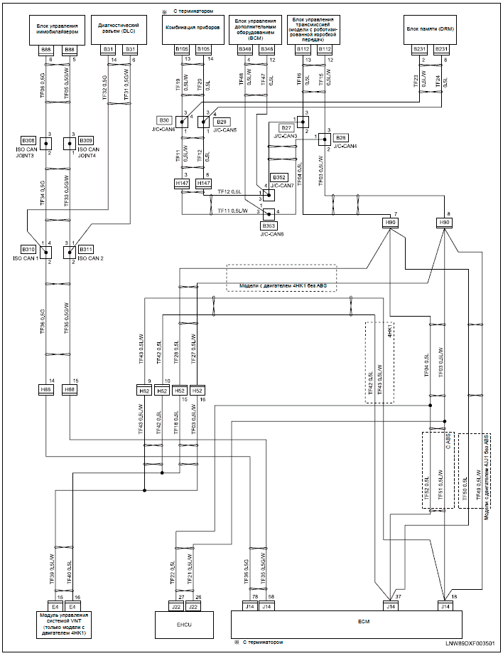
2. 3 York Drive.TECHNICAL GUIDE % SINGLE STAGE GAS-FIRED RESIDENTIAL MULTI-POSITION GAS FURNACES product improvement, specifications are subject to change without notice.
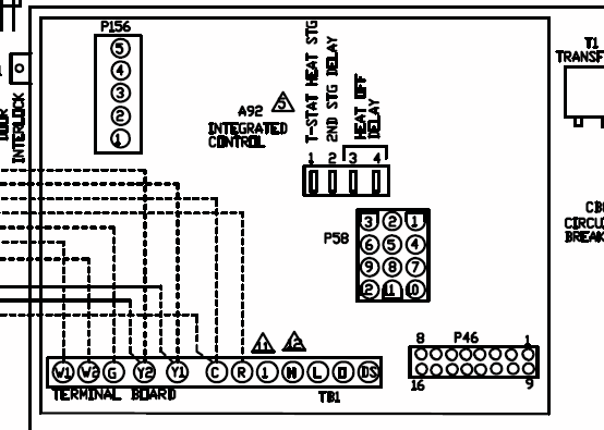
Visit us on the web at schematron.org and schematron.org Additional rating information can be found at schematron.org refer to the UPGNET “Low Voltage Wiring Diagram”. York Retail System Specific Wiring Diagrams York System Wiring Diagram WD 1.
Optional. Optional. NOTES: If wires between the Air Handler and the Heat Pump is not possible W1 and W2 can be combined at the AH.

York System Wiring Diagrams WD 3. Optional. Optional * .
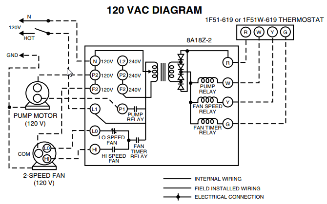
WIRING DIAGRAM CONTRACTOR _____ PURCHASER _____ FIelD CoNNeCtIoNs AND CoNtRol WIRING FoR YvWA ChIlleR JoB DAtA: CHILLER (PIN ) YVWA Terminal Block for YORK Connections Wiring Components by YORK Optional Equipment Wiring and/or Components by Others Note Well A Component Marked Thus is External to the. DISCLAIMER. This material is for professional use only and is intended to be used only as reference material by licensed contractors when installing or servicing Reznor equipment.
Nortek Global HVAC/Reznor does not endorse any field changes to factory wiring schemes. York DNP Technical Manual.
TYPICAL WIRING DIAGRAM NOTES All field wiring to be accomplished following city, local and/or national codes in effect at time of installation of this unit. Caution: Label all wires prior to disconnection when ser- vicing controls.
YORK’s DNP is a unit that gives you the flexibility and choices you need.How to Wire an Air Conditioner for Control – 5 WiresYORK DNP TECHNICAL MANUAL Pdf Download.