To troubleshoot electrical issues in your 2004 vehicle, start by consulting the layout of the control units within the cabin and engine compartments. Identifying the proper relay or circuit connection can save time and avoid unnecessary component replacements.
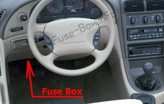
Know the location of key control units–each vehicle is equipped with multiple control panels, and the 2004 model has them positioned for ease of access. Typically, one is found under the dashboard on the driver’s side, while the other may be located near the engine area. Be sure to locate these areas before beginning your diagnostic process.
Familiarize yourself with the connections and their labels. Each unit has specific labeling for various systems such as lighting, ignition, and air conditioning. Double-check these labels and verify that they match the current problem you’re facing. If a circuit is faulty, knowing the specific relay or connection will help you address the issue directly without unnecessary guesswork.
If you’re replacing a component or checking the functionality of certain parts, ensure you’re working with accurate labels and symbols. Proper reference to these connections helps maintain the integrity of the vehicle’s electrical system and ensures that no components are inadvertently damaged during troubleshooting.
Electrical System Layout for the 2004 Vehicle
The primary electrical components are located within the central distribution unit behind the dashboard. For troubleshooting, always start by checking the relays that control critical systems such as lighting and engine management.
For convenience, use a detailed chart to identify the specific circuits connected to each terminal. Commonly, this unit will feature separate clusters: one for high-amperage circuits like the starter motor and another for low-current devices such as the infotainment system.
In case of issues like blown circuits or intermittent power, focus first on checking the main connections to avoid unnecessary disassembly. The unit will typically have a cover that can be easily removed for access to the wiring connections.
Key sections include a set of fuses related to ignition, a set for HVAC systems, and a few for ancillary features such as windows and mirrors. Each of these circuits will typically be color-coded or labeled for easy identification.
Always verify the amperage ratings listed on the cover or the attached label. For replacements, ensure you use the same ratings to avoid damage to the vehicle’s wiring. If a fuse blows frequently, this may indicate an underlying issue, such as a short circuit or overdrawn current, requiring professional inspection.
Identifying Circuit Protection Locations and Functions in the 2004 Model

For quick access, refer to the under-hood compartment and interior panels to locate the electrical component safety systems. The engine bay compartment contains the main system, while the cabin features additional access points near the driver’s seat area and under the dashboard.
Each slot is specifically assigned to components like lights, ignition, HVAC system, and interior electronics. In the main compartment, larger components like the alternator or air conditioning are usually safeguarded by higher-rated circuits, while smaller ones, such as windows or mirrors, use lower-rated connections.
Interior systems, especially for the radio, wipers, and seat adjustments, are commonly secured through their dedicated network found within the cabin area. Ensure to check that any malfunctioning parts match their corresponding protection. For instance, a faulty climate control system might be due to a blown link found in the panel near the driver’s side.
For ease of maintenance, always keep a spare set of the protection elements in the vehicle, especially the smaller ones used for cabin lights or entertainment systems. Check each area periodically to ensure proper function, as electrical overloads or short circuits are common causes of damage to these connections.
How to Replace a Blown Fuse in the 2004 Mustang

Locate the power distribution panel under the hood on the driver’s side near the strut tower. Use the plastic pull tab to lift the cover.
- Turn off the ignition and disconnect the negative battery terminal to prevent short circuits.
- Refer to the inside of the lid for the slot layout. Identify the failed component and match it to its corresponding slot number.
- Inspect the translucent element by holding it to the light–if the metal strip is severed, it must be changed.
- Use a removal tool or needle-nose pliers to extract the damaged piece without damaging adjacent terminals.
- Insert a replacement of the same amperage rating. Never substitute with a higher value, as it risks wire damage or fire.
Examples of common ratings:
- 15A – for audio or lighter outlets
- 20A – for power windows or wipers
- 30A – for cooling fans
After installation, reconnect the battery terminal and test the system. If the part fails again, check for a short or overload in the related circuit.
Understanding Circuit Protection in the 2004 Mustang Fuse Panel
Check the interior relay center under the driver’s side dash for blown micro fuses, especially slot #2 (15A) for the instrument cluster and slot #8 (10A) for power mirrors. These are common failure points when electrical accessories malfunction.
Under the hood, inspect the power distribution module near the battery. Slot #104 (30A) protects the cooling fan circuit; a failed component here often leads to overheating. Slot #111 (40A) handles the anti-lock braking system–replace it only with an identical amperage rating to avoid brake system failure.
Avoid using generic replacements. Always match the color and current rating to the original. For example, replace a 20A yellow unit in position #18 (cigar lighter) with an exact equivalent to prevent socket damage.
To disable a specific accessory temporarily, remove its corresponding mini blade from the cabin panel. For example, slot #12 (15A) cuts off the audio system safely during troubleshooting.
Use a multimeter to verify voltage presence across terminals. No power at a live slot usually indicates a deeper issue like a faulty relay or severed wire rather than a blown protective element.