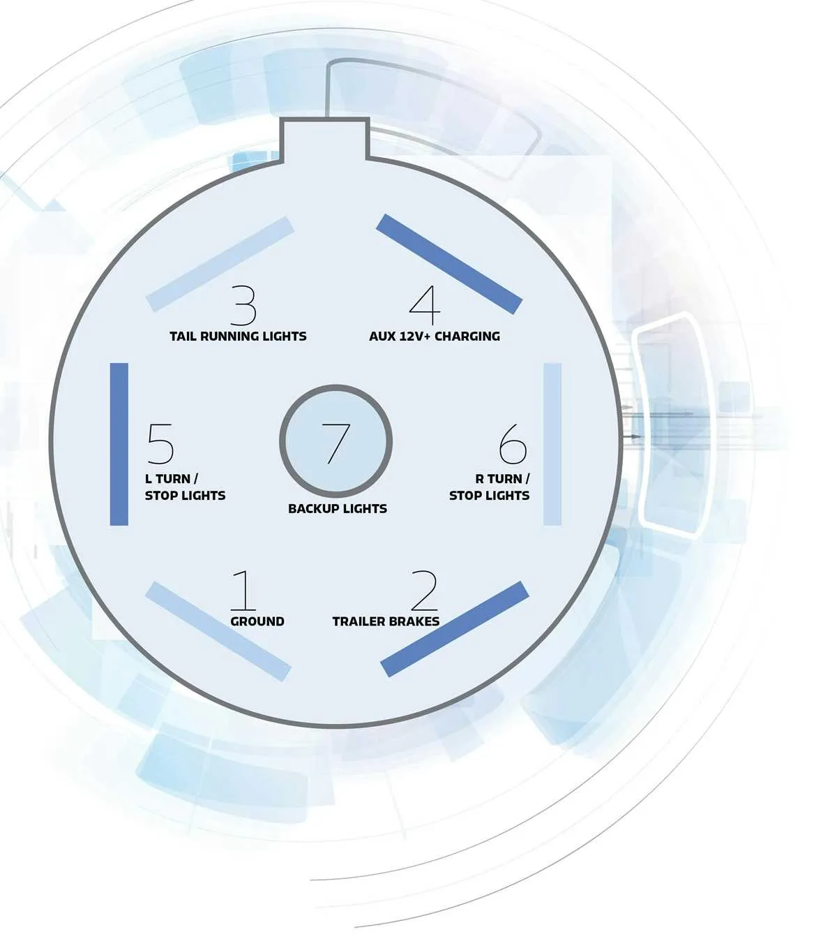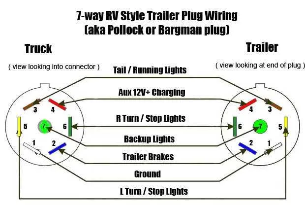
To ensure proper functionality and safety when connecting your towing system, start by understanding the essential color-coding and pin assignments for a 7-pin connector. Each pin corresponds to a specific electrical function needed for the vehicle and trailer interaction.
Pin 1 is typically assigned to the ground wire, which completes the circuit for the electrical system. Make sure it is securely connected to the vehicle’s chassis for a reliable connection.
Pin 2 often carries the reverse signal, which is crucial for reversing the trailer without activating the towing vehicle’s brake lights. Connect this pin to the reverse light circuit on the towing vehicle for seamless functionality.
Pin 3 is designated for the left turn signal. Verify that this wire is linked to the vehicle’s left turn signal output to ensure the signal is correctly transmitted to the trailer lights.
Pin 4 handles the right turn signal, just as Pin 3 does for the left. This pin should be wired to the vehicle’s right turn signal system to complete the circuit for turn signal synchronization.
Pin 5 typically powers the trailer’s brake lights. Make sure it is correctly connected to the towing vehicle’s brake light circuit to ensure the brake lights activate when needed.
Pin 6 carries the running lights signal. This wire must be connected to the vehicle’s running lights to ensure the trailer lights remain on when the vehicle’s lights are activated.
Pin 7 is usually reserved for auxiliary power, often used to charge the trailer’s battery or supply additional power to trailer features. Make sure the wire is properly sized to handle the power requirements of the trailer’s additional functions.
GM Connector Pinout Guide
To ensure proper functionality, connect each wire to the following pins of the GM connector:
Pin 1: Ground – This pin should be connected to a solid grounding point on the vehicle to prevent electrical faults.
Pin 2: Left Turn Signal – Link this pin to the left signal light circuit.
Pin 3: Right Turn Signal – This pin is for the right turn signal connection.
Pin 4: Brake Light – Connect this to the brake light system to activate when the vehicle brakes are engaged.
Pin 5: Backup Lights – For proper backup lighting, this pin needs to be wired to the reverse light circuit.
Pin 6: Electric Brake – This pin sends voltage to the trailer’s braking system when activated.
Pin 7: 12V Power – This provides a continuous power supply, suitable for charging or powering auxiliary systems on the connected unit.
Identifying Pinouts for GM 7-Way Trailer Plug

To ensure proper connection, start by identifying each pin’s function. Begin with the first pin on the left, which is responsible for the ground. It is typically marked with a white wire. The second pin is for the tail lights, usually paired with a brown wire. The third pin controls the left turn signal, identified by a yellow wire. The fourth pin connects to the brake lights, generally using a red wire.
Next, the fifth pin is used for the right turn signal, usually indicated with a green wire. The sixth pin supports the backup lights and is commonly marked with a blue wire. Finally, the seventh pin is dedicated to the electric brake system, which is typically wired with a black or purple wire. Double-check each connection to avoid mismatches and ensure proper functionality.
Understanding Color Codes and Their Functions
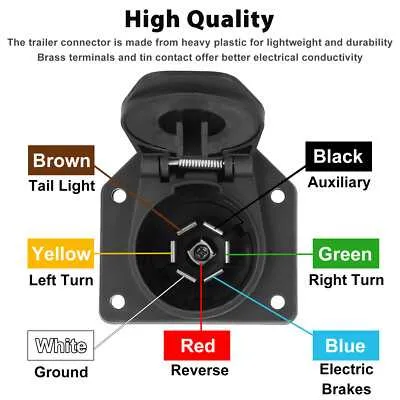
Always match the brown wire to the tail and marker lights circuit; it supplies power to rear illumination during nighttime driving.
Connect the yellow wire directly to the left turn signal and stop light; it carries pulsed voltage from the tow vehicle’s flasher circuit.
Use the green wire for the right turn indicator and brake light; it mirrors the yellow circuit but serves the opposite side.
The blue wire is designated for electric brake control; it delivers variable voltage from the in-cab controller based on braking intensity.
Assign the white wire exclusively to the ground return path; bolt it securely to a clean, bare metal surface on the towing frame.
The black wire handles the auxiliary power feed, typically 12V, supplying charge to onboard batteries or running interior systems.
Utilize the purple wire (or sometimes grey) for reverse lights; it activates rear-facing lamps when the tow vehicle is shifted into reverse gear.
Step-by-Step Guide to Wiring GM 7-Way Trailer Plug

Use a multimeter to confirm each circuit function before connecting any leads. Ensure the battery is disconnected to prevent shorts.
- Identify each terminal on the connector. Most GM configurations follow this standard:
- 12 o’clock – Reverse signal (center top)
- 2 o’clock – Ground (white)
- 4 o’clock – Right brake/turn (green)
- 6 o’clock – Stop lamps (red or blue, depending on year)
- 8 o’clock – Left brake/turn (yellow)
- 10 o’clock – Running lights (brown)
- Center – Battery charge or auxiliary (black)
- Strip 1/4″ insulation from each conductor, crimp ring or spade terminals as needed.
- Insert each wire into its designated location. Verify alignment before tightening the screws.
- Secure the harness with weatherproof tape or heat shrink tubing to prevent corrosion.
- Reconnect the vehicle battery and test each function using a tester or connected equipment.