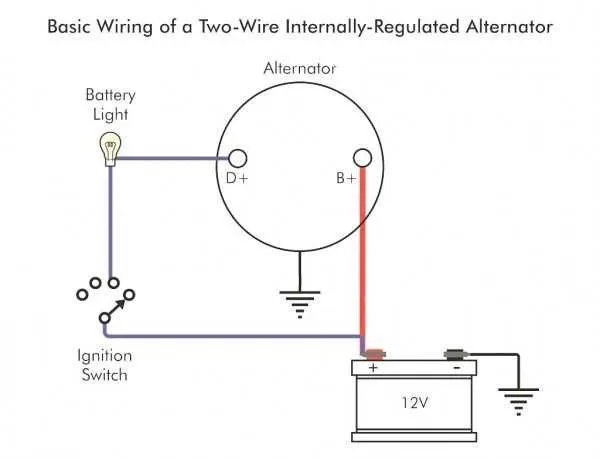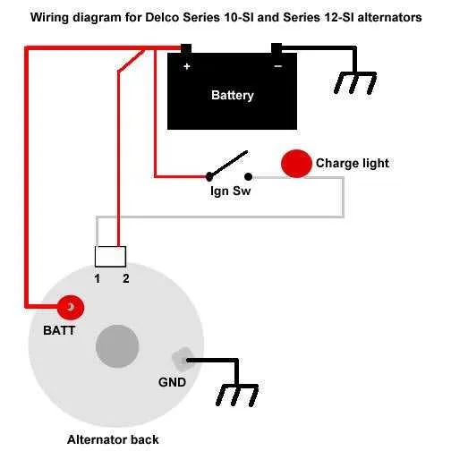
For reliable performance with a simplified electrical generator installation in Chevy vehicles, use a direct hookup system that minimizes complexity and maximizes output efficiency. Connect the power output terminal directly to the battery positive post, ensuring a secure and clean link that supports consistent charging under all operating conditions.
Key tip: Incorporate a high-quality inline fuse or circuit breaker rated appropriately for your charging system’s amperage to protect the main cable and electrical components from potential faults. This enhances safety and extends the lifespan of your setup.
Ensure the ground connection is solid and free from corrosion by attaching the chassis grounding point near the engine block. This reduces voltage drops and maintains stable current flow throughout the charging circuit. Use properly gauged cable to handle the expected electrical load without overheating.
Optimization advice: Utilize a regulator integrated within the generator housing or an external module designed for Chevy models to maintain voltage within specified limits. This prevents overcharging and damage to sensitive electronics while providing steady power for vehicle operation.
1 Wire Generator Connection Guide for Chevy

Connect the single-terminal generator output directly to the positive battery post through a properly rated fuse or fusible link to ensure optimal charging performance and safety. Use a heavy-gauge cable (minimum 8 AWG) to handle the charging current and prevent voltage drops.
Ground the unit’s casing securely to the engine block or chassis to complete the circuit and maintain voltage stability. Avoid routing the main lead near heat sources or moving parts to reduce insulation damage risk.
Ensure the ignition key is in the “ON” position before starting the engine to activate the internal regulator. Confirm all connections are tight and corrosion-free to maintain reliable power flow and avoid charging issues.
For best results, use terminals rated for high current and apply dielectric grease to prevent oxidation. When upgrading, select a generator model compatible with your vehicle’s electrical system voltage (typically 12V for Chevrolet models).
How to Identify the Correct Single-Connection Generator for Chevy Models
Choose a charging unit designed specifically for your vehicle’s year and engine type. Follow these steps to ensure compatibility:
- Check the output rating: Most factory replacements range from 60A to 105A depending on the engine size and electrical load.
- Match the mounting style: Confirm whether your vehicle uses a traditional bracket or a specialized mounting setup to avoid fitment issues.
- Verify the pulley type: Determine if a V-belt or serpentine pulley is required based on the front accessory drive system.
- Inspect the internal regulator: Some models require an internal voltage regulator; ensure your unit includes it or plan for an external regulator.
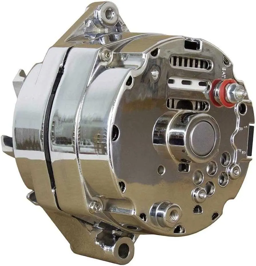
- Confirm terminal type: For a single-connection setup, the generator must have a single output stud and appropriate grounding configuration.
Utilize factory part numbers and cross-reference aftermarket codes to avoid incompatibility. Avoid units intended for multi-connection systems as they may cause charging failures or electrical faults.
Step-by-Step Guide to Connecting a 1 Wire Generator on Chevy Vehicles

Begin by disconnecting the battery to ensure safety during installation. Locate the output terminal on the single-lead charging unit; this terminal must connect directly to the positive post of the battery or starter solenoid using a heavy-gauge cable (minimum 8 AWG) to handle high current.
Ensure the mounting bracket grounds the housing firmly to the engine block for a reliable electrical path. If necessary, attach a dedicated grounding strap from the body of the charging device to the chassis to prevent charging issues.
Remove any factory-installed voltage regulator or external control wiring; this type of generator is self-regulating and requires no additional connections. Verify that the ignition switch does not supply voltage to the charging component; otherwise, disconnect that circuit to avoid backfeed.
Inspect the pulley alignment to prevent belt slippage or premature wear. Use a tensioner or adjust the alternator’s position so the belt maintains proper tension according to manufacturer specifications (usually around 1/2 inch deflection under moderate pressure).
Reconnect the battery and start the engine. Use a multimeter to measure voltage at the battery terminals; it should read between 13.8 to 14.5 volts under normal operating conditions, indicating proper charging function. If voltage is low, check all connections for corrosion or looseness.
Secure all cables with appropriate clamps or ties to prevent contact with moving parts or hot engine surfaces. Perform a final inspection to confirm no exposed conductors or potential short circuits exist.
Troubleshooting Common Issues with Chevy 1 Wire Alternator Connections
Start by verifying the main power lead for a secure, corrosion-free connection at both the generator and battery terminals. Loose or oxidized contacts cause voltage drops and charging failures. Use a digital multimeter to check output voltage; it should register between 13.8V and 14.5V during engine operation.
If charging is inconsistent, inspect the grounding point of the charging device’s housing. A poor chassis ground often results in erratic performance or no charge at all. Clean the surface thoroughly and ensure a tight bolt connection.
Check the internal regulator’s operation by measuring voltage changes when the engine speed varies. If voltage remains static or below threshold, the regulator may be faulty and require replacement.
Examine the primary lead for damage, fraying, or overheating signs, especially near bends or mounting points. Any compromised insulation or conductor can interrupt current flow.
Ensure the starter solenoid or fuse linked to the main power circuit is intact and free of corrosion. A blown fuse or faulty relay will interrupt the charging system’s activation.
For persistent low output, test the rotor field by injecting a small voltage and measuring the magnetic response. Failure here points to worn brushes or slip rings needing servicing.
Replace any suspect connectors with high-quality terminals and apply dielectric grease to prevent moisture ingress and future corrosion.