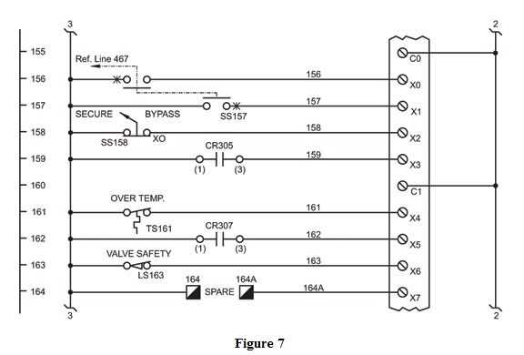
The 1734 OB4 is a digital output module designed for use in industrial automation applications. It is part of the Allen-Bradley POINT I/O system and provides four isolated outputs for controlling various devices and equipment.
Understanding the wiring diagram for the 1734 OB4 module is essential for successful installation and operation. The diagram outlines the connections between the module and other components in the system, including power supply, field devices, and communication network.
The wiring diagram typically includes information about the terminal assignments for input and output connections, as well as any jumpers or switches that may need to be set. It provides details on the power requirements, such as voltage and current ratings, and indicates any additional components, such as fuses or surge protectors, that are necessary for proper operation.
Proper wiring of the 1734 OB4 module is crucial for ensuring reliable and accurate control of devices in an industrial setting. By following the wiring diagram and understanding the connections, users can confidently integrate the module into their automation system and optimize its performance.
Understanding the basics

In order to comprehend the wiring diagram for the 1734 ob4 module, it is essential to have a fundamental understanding of its basics. The 1734 ob4 module is a digital output module used in control systems to interface with external devices. It is designed to provide high-speed, reliable output signals to control various devices such as motors, lights, and solenoids.
The wiring diagram for the 1734 ob4 module details how the module should be connected to the control system and the external devices. It includes information on the terminal numbers, wire colors, and connection points for each input and output. Understanding this diagram is crucial for proper installation and troubleshooting.
To properly interpret the diagram, it is important to know the different components and symbols used in it. The diagram may consist of blocks representing the 1734 ob4 module, the control system, and the external devices. Arrows indicate the flow of signals between these components. Terminal blocks are used to connect the wires, and each wire is labeled with a specific color.
Additionally, the diagram may include labels indicating the purpose of each input and output. Inputs are used to send signals from external devices to the control system, while outputs are used to send signals from the control system to the external devices. Understanding the purpose of each input and output is crucial for configuring the control system correctly.
In conclusion, understanding the basics of the 1734 ob4 module and its wiring diagram is vital for proper installation and troubleshooting. By familiarizing yourself with the components, symbols, and labels used in the diagram, you can effectively connect the module to the control system and external devices.
Step-by-step Instructions for Wiring the 1734 OB4
Wiring the 1734 OB4 module to your control system is a straightforward process that can be completed in a few simple steps. By following these step-by-step instructions, you can ensure a successful installation and integration of the OB4 module into your system.
Step 1: Start by gathering all the necessary tools and equipment before beginning the wiring process. This includes a screwdriver, wire stripper, pliers, and any additional wiring components that may be required.
Step 2: Next, identify the appropriate location in your control system where the 1734 OB4 module will be installed. Ensure that it is placed in a suitable position that allows for easy access and connections to other components.
Step 3: Now, take the power supply wires and connect them to the appropriate terminals on the 1734 OB4 module. Make sure to follow the manufacturer’s guidelines for the correct wiring configuration.
Step 4: Once the power supply wires are connected, take the input and output wires and connect them to the corresponding terminals on the module. Use the wire stripper to remove any insulation from the wire ends before making the connections.
Step 5: After all the connections have been made, securely tighten the terminals using a screwdriver. This will ensure a reliable and stable electrical connection.
Step 6: Finally, double-check all the connections to ensure they are properly secured and that there are no loose wires or connections. Test the module to verify that it is functioning correctly within your control system.
By following these step-by-step instructions, you can confidently wire the 1734 OB4 module in your control system. Remember to always refer to the manufacturer’s documentation and guidelines for any specific instructions or requirements.
Troubleshooting common issues
When working with the 1734-OB4 module and its wiring diagram, there are a few common issues that may arise. Troubleshooting these issues is crucial for ensuring proper functionality.
1. Incorrect wiring connections
One common issue is incorrect wiring connections, which can lead to various problems. It is important to carefully follow the wiring diagram provided by the manufacturer to ensure that all connections are made correctly. Check all terminal connections and ensure they are properly tightened. If there is any doubt about the wiring, consult the wiring diagram or seek assistance from a qualified technician.
2. Faulty power supply
A faulty power supply can also cause issues with the 1734-OB4 module. Ensure that the power supply is delivering the correct voltage and current as specified in the module’s documentation. Check for any loose connections or damaged wires in the power supply circuit. If necessary, replace the power supply to eliminate this potential issue.
3. Incompatible devices
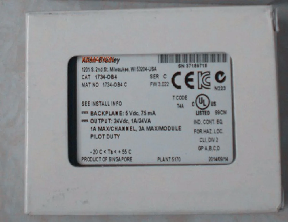
Sometimes, compatibility issues may arise when using the 1734-OB4 module with other devices. Ensure that all connected devices are compatible with the module and are properly configured. Check the specifications and documentation of the devices to ensure compatibility. If devices are not compatible, consider using compatible devices or seeking alternative solutions.
4. Module configuration errors
Incorrect module configuration can also cause issues with the 1734-OB4 module. Check the module’s configuration settings and ensure that they are correctly set according to the desired operation. Consult the module’s documentation for guidance on the correct configuration procedures. If necessary, reset the module to its default settings and reconfigure it as per the requirements.
By troubleshooting these common issues, users can ensure the proper functioning of the 1734-OB4 module and avoid any operational problems. It is important to refer to the module’s documentation and seek professional assistance if needed to resolve any issues effectively.
Best Practices for Installation
Proper installation is crucial for the efficient and safe operation of the 1734 ob4 module. Here are some best practices to follow:
1. Read the Manual
Before starting the installation process, it is essential to thoroughly read the installation manual provided by the manufacturer. The manual will provide detailed instructions and guidelines specific to the 1734 ob4 module, ensuring a successful installation.
2. Plan the Layout
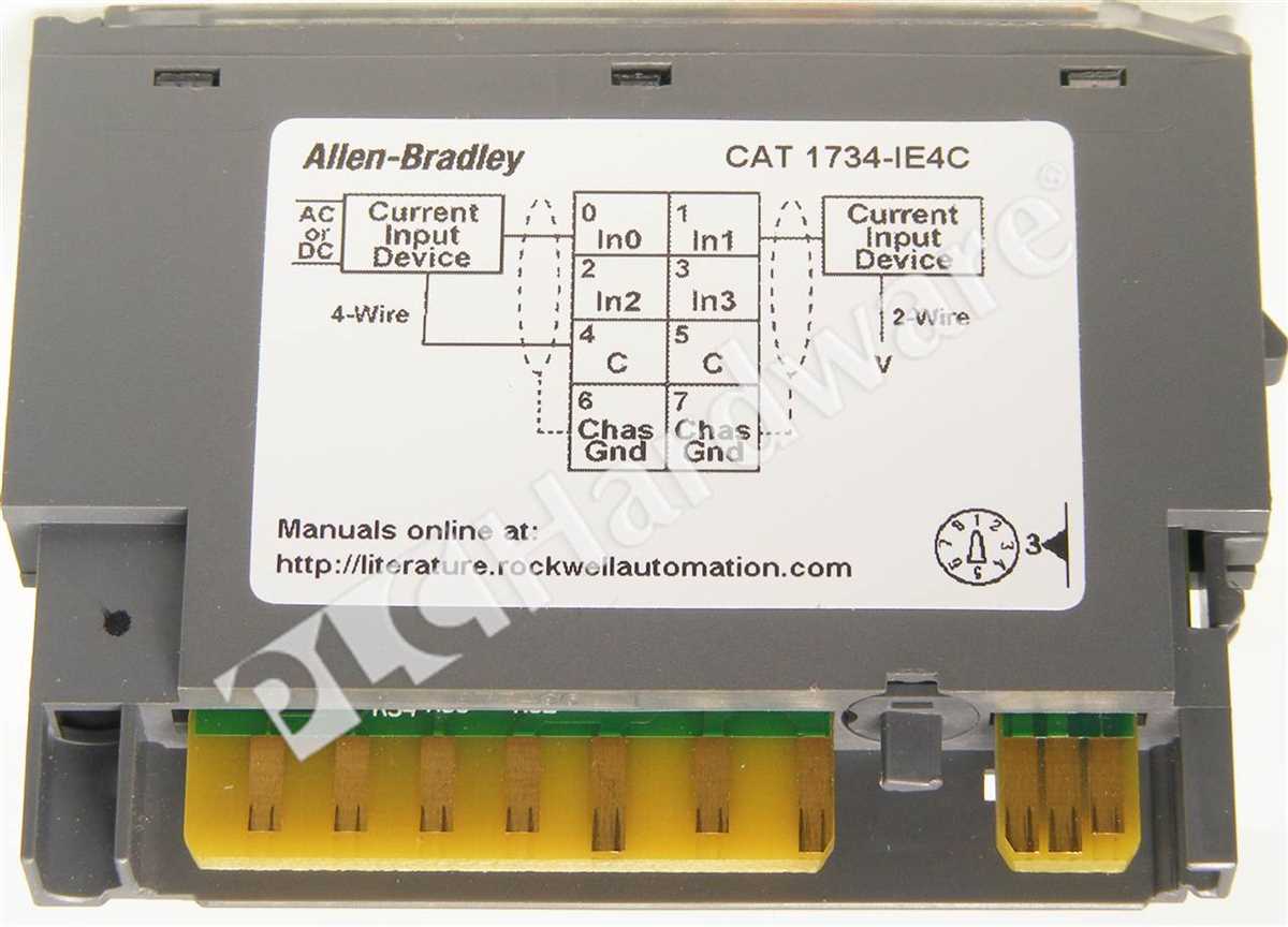
Before installing the module, carefully plan the layout of the wires, terminals, and connections. This step will help prevent any potential issues or confusion during installation. Additionally, it is essential to consider the overall space required for the module and make sure it fits properly in the desired location.
3. Use Proper Tools and Equipment
Make sure to use the appropriate tools and equipment for the installation process. This includes wire strippers, screwdrivers, and pliers, among others. Using the correct tools will ensure a secure and reliable connection and minimize the risk of damage to the module or other components.
4. Follow Safety Guidelines
Always prioritize safety during the installation process. Ensure that the power to the system is turned off before starting any work. Additionally, follow all relevant safety guidelines, such as wearing appropriate personal protective equipment and using caution when handling electrical components.
5. Check Connections
After completing the installation, double-check all connections to ensure they are secure and correctly installed. Loose connections can lead to unreliable performance or potential safety hazards. Take the time to inspect each connection individually and remedy any issues as needed.
Conclusion
Following these best practices for installation will help ensure a smooth and successful process when installing the 1734 ob4 module. Proper installation is essential for maximizing performance, maintaining safety, and preventing potential issues. By carefully planning, using the correct tools, and adhering to safety guidelines, you can confidently install the module and have it ready for use.