If you’re working with the 1756 OA16 module and need to configure its electrical connections, it’s essential to follow the correct sequence to ensure functionality and avoid errors. The module’s terminal layout includes specific input and output pins that correspond to various types of signals. Familiarizing yourself with these pins and their specific use cases can save time during setup.
Each terminal block on this device is designed for different types of electrical signals–whether you’re dealing with analog or digital systems. Pay close attention to the numbering and placement of each connection to prevent short circuits or signal interference. If you’re unsure, always refer to the manual for exact pinout details.
Tip: For optimal performance, make sure that the power supply voltage matches the module’s specifications. A mismatched supply can cause instability or prevent the module from working altogether. Regular checks for secure connections can prevent long-term issues.
Note: When setting up this module in a rack system, ensure that there’s proper grounding and that the input/output wiring matches the expected standards for your configuration. This avoids potential system failures or incorrect data transmission.
Wiring Connections for the OA16 Module
When connecting the I/O module, always ensure that the power supply meets the required specifications for optimal functionality. The inputs on the terminal block should be securely attached to prevent signal loss or voltage fluctuation. Verify the polarity for each connection before finalizing the setup, especially for differential signals.
For output connections, use shielded cables where necessary to minimize electrical noise and ensure signal integrity. Cross-check each wire against the module’s pinout guide, particularly for any high-voltage or high-current components, to avoid damage to the system.
During installation, leave adequate space between the module and adjacent equipment to maintain proper airflow for heat dissipation. A compact setup may result in overheating and reduced performance over time.
If you’re working with analog signals, ensure that the grounds are properly referenced to avoid ground loops that could interfere with the signal quality. Grounding should always be consistent across all components for reliable operation.
Double-check all connections using a multimeter or continuity tester to confirm there are no short circuits or miswiring before powering up the system. This can prevent costly repairs and ensure long-term reliability.
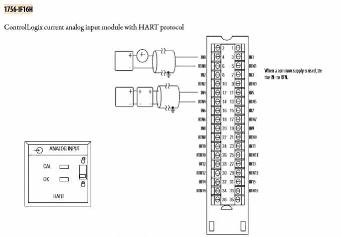
Understanding the Pinout and Connection Points for 1756 OA16

Identify the proper input/output pins for accurate device communication. The connection layout includes multiple signal terminals arranged in a clear sequence. Each pin must be properly assigned for optimal signal integrity. Pay attention to voltage levels, as mismatches can lead to device failure or improper operation. Ensure all grounds are securely connected to prevent erratic behavior or malfunctioning.
The inputs are generally aligned in pairs, allowing for efficient processing of binary signals. Pin 1 serves as the primary input for the first channel, while subsequent pins correspond to additional channels. Output pins, often located near the corresponding inputs, follow a similar structure. Labeling each connection clearly in your setup is vital to prevent confusion during installation and troubleshooting.
When wiring multiple devices, ensure that each connection point is firm and free from corrosion. A loose connection can cause intermittent behavior or system errors. Use appropriate shielding if the device is placed in environments with high electromagnetic interference (EMI), as this could impact signal transmission quality.
For applications requiring high-speed data transfer, ensure that the connecting cables are of adequate quality and specification. Keep cables as short as possible to reduce signal degradation. In environments with potential surges or power spikes, consider installing surge protection to safeguard against damage to the electronic components.
Troubleshooting Common Electrical Connection Issues
Start by checking for loose or disconnected terminals, as poor contact is a frequent cause of signal loss or malfunction. Ensure all connections are tightly secured, especially for input and output pins. Loose connections often result in intermittent or failed operations.
Next, confirm proper grounding of the system. Incorrect grounding can lead to electrical noise or erratic behavior in your system. Always verify the ground connections using a multimeter to ensure there is continuity between the device and the ground point.
If voltage readings appear incorrect, inspect the power supply unit for instability. Fluctuating or low voltage can cause the device to behave unpredictably. Test the power inputs to ensure they match the required specifications outlined in the technical documentation.
Check for shorts by inspecting the cables for any visible wear or damage. Shorts between adjacent conductors can cause system failure or even permanent damage to internal components. Replace any frayed or damaged cables immediately to avoid further issues.
Ensure that the current load on the device is within acceptable limits. Overloading the input or output channels may cause failure to activate or even burn out components. If necessary, reduce the load or distribute the current across multiple channels to prevent overstrain.
Finally, use diagnostic tools like oscilloscopes or signal analyzers to monitor the behavior of the system under normal operating conditions. This can help detect subtle issues like voltage spikes or incorrect signal timing that might not be immediately apparent with basic measurements.
Step-by-Step Guide to Properly Connecting the Control Module to System Components
Follow these steps to ensure correct connection between the control module and your system.
- Verify that all power sources are turned off before starting the installation process.
- Identify the terminal blocks and pinouts on the module. Ensure you have the correct wiring specifications for your system’s voltage and current.
- Connect the power supply lines to the module’s input terminals, ensuring proper polarity. Typically, these will be labeled as V+ and V- for DC connections or L and N for AC systems.
- Next, connect the input channels to the desired devices (sensors or switches). Check for any specific wiring color codes or conventions used by the system.
- For output connections, refer to the pinout to correctly wire relay or control outputs. Double-check the load specifications to prevent overloading.
- If your system includes an I/O module for communication, ensure the signal cables are securely connected to the designated communication ports. This may include RS-232, RS-485, or Ethernet-based connections, depending on your configuration.
- Ground the module to the system’s grounding point to prevent electrical interference and ensure safety. A proper ground connection is critical for stable performance.
- Once all connections are made, perform a continuity test to ensure there are no shorts or incorrect wiring.
- Power up the system and check for normal operation. Monitor the signals and status indicators to confirm correct functionality.
By following these instructions, you can ensure proper and reliable connections for your control system integration. Always consult the product manual for additional specifics or system requirements.