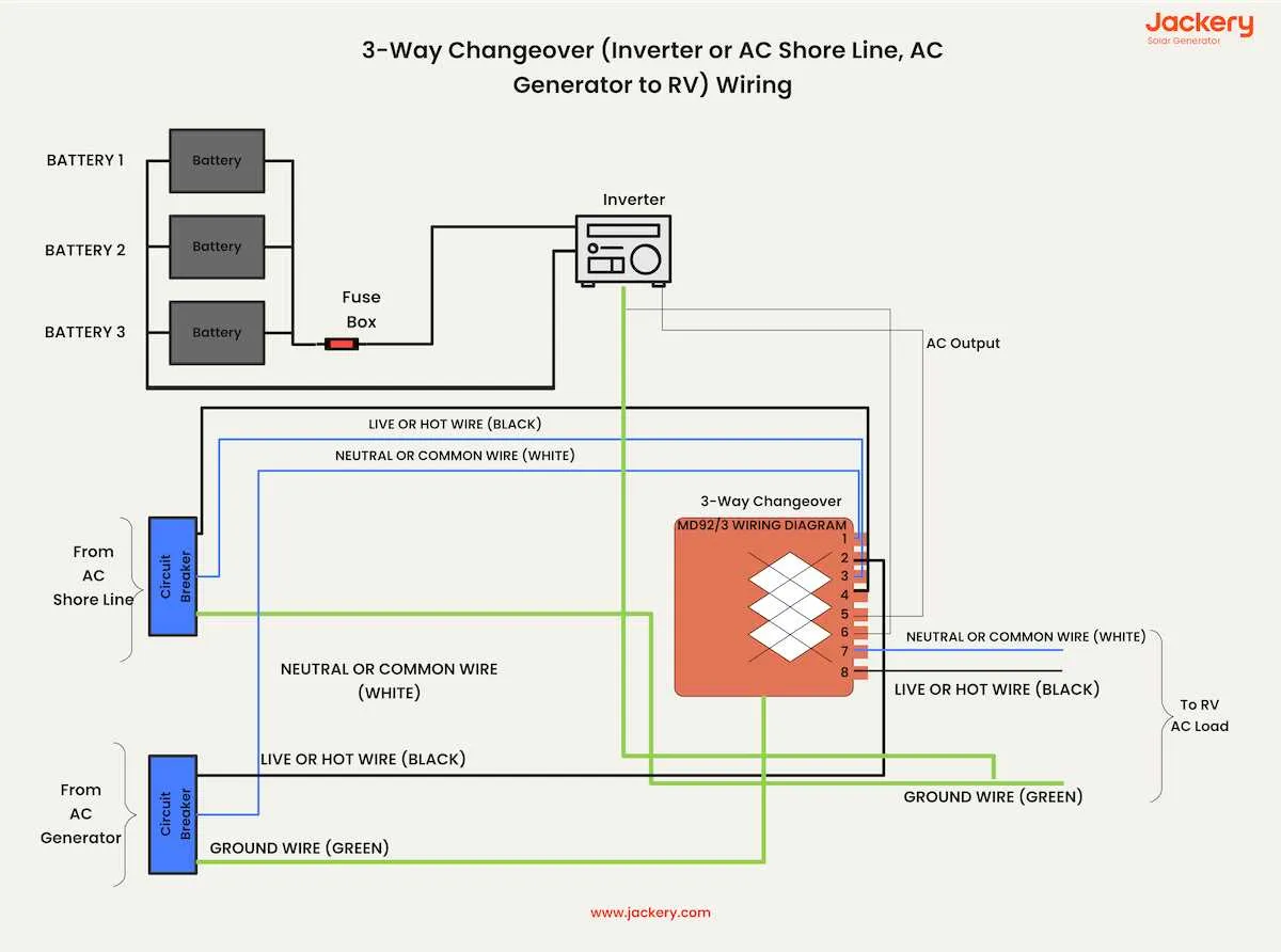
For efficient integration of a power converter into an RV’s electrical system, connect the AC input lines directly to the main distribution panel. Ensure that the converter’s output terminals feed the DC bus through appropriate fuses or circuit breakers rated for the system’s amperage.
Use color-coded cables to distinguish between positive and negative DC circuits, and maintain consistent polarity to avoid damage to onboard electronics. The grounding point must be common for both the converter and chassis to minimize electrical noise and prevent voltage spikes.
Position the power conversion device near the battery bank for shorter cable runs, reducing voltage drop. Incorporate a dedicated disconnect switch to isolate the unit during maintenance or emergency situations. Follow manufacturer specifications for wire gauge selection based on current load to ensure safety and reliability.
RV Electrical Setup Incorporating Power Converter
Connect the power converter directly to the battery bank using properly rated cables–minimum 8 AWG for systems under 50 amps. Use a dedicated fuse or circuit breaker near the battery terminal to protect the line. The converter’s output must feed the distribution panel, ensuring all 12V circuits receive stable current.
Install a transfer switch to safely alternate between shore power and the power converter source. This prevents backfeeding and safeguards sensitive electronics. Position the transfer device close to the main breaker panel for accessibility.
Grounding is critical: link the converter chassis to the RV’s main grounding bus to avoid electrical noise and reduce shock risk. Check all connectors for corrosion and ensure tight, secure contacts to maintain efficiency and prevent voltage drops.
When integrating the power source that converts DC to AC, place it near the battery compartment but ensure proper ventilation to avoid overheating. Use heavy-gauge cables (minimum 4 AWG) for connections between the battery bank and the power source to handle surge currents during peak loads.
Include a remote monitoring panel or voltage meter to track battery health and load demands. This aids in preventing deep discharge and extends battery lifespan. Confirm that the power distribution panel’s breakers match the expected load to avoid nuisance trips.
How to Integrate an Inverter into Existing RV Electrical System
Connect the power conversion device directly to the RV’s battery bank using appropriately gauged cables to ensure minimal voltage drop and safe current flow.
- Disconnect the main power source before beginning installation to prevent electrical hazards.
- Locate the battery terminals and install a fuse or circuit breaker within 12 inches of the positive battery post to protect against short circuits.
- Use heavy-gauge cables (typically 4 AWG or thicker, depending on inverter capacity) to link the power unit to the batteries.
- Ground the negative terminal securely to the RV chassis to maintain system stability and reduce interference.
- Route cables away from heat sources, sharp edges, and moving parts to prevent damage.
Integrate the output connections into the RV’s AC distribution panel by:
- Installing a transfer switch or automatic transfer relay to manage power source switching between shore power and the power conversion device.
- Connecting the device output to a dedicated breaker in the distribution box, sized according to the unit’s continuous amperage rating.
- Ensuring proper bonding and grounding throughout the AC system to comply with safety standards.
After completing connections, perform a voltage test at the battery terminals and output panel to verify correct polarity and stable power delivery before re-energizing the system.
Step-by-Step Guide to Connecting Battery, Power Converter, and AC Outlets in RV
Begin by securing a 12V deep cycle battery in a well-ventilated compartment, ensuring terminals are clean and corrosion-free. Attach heavy-gauge positive and negative cables directly to the battery posts, using properly rated ring terminals and insulated connectors.
Next, connect the DC leads to the power conversion unit, observing polarity to prevent damage. Use fuse holders or circuit breakers rated slightly above the maximum current draw between battery and converter for safety.
Run the AC output cables from the power conversion device to a dedicated breaker panel, making sure all neutral and ground wires are properly bonded according to electrical codes. Install individual circuit breakers for each outlet to isolate loads efficiently.
For outlet connections, use three-prong grounded receptacles rated for at least 15 amps. Secure all terminals tightly and enclose connections in weatherproof boxes if outlets are exposed.
Test the entire setup by measuring voltage at each outlet while under load, confirming stable output and absence of voltage drops. Verify that breakers trip appropriately when overloaded to ensure protective measures function correctly.
Troubleshooting Common Issues in RV Power Setup
Start by verifying all electrical connections between the energy converter and battery system are secure and corrosion-free. Loose terminals or oxidized contacts often cause intermittent power loss or failure to transfer energy properly.
Check the gauge of cables used; undersized conductors create voltage drops, leading to poor performance or overheating. Use at least 4 AWG for high-current lines and ensure cables run directly without unnecessary splices.
Inspect fuses and circuit breakers along the control path for signs of wear or damage. Replace any components showing discoloration or melting to prevent dangerous shorts or interruptions.
Confirm polarity at each junction point. Reversed positive and negative leads can damage sensitive electronics and trip protective devices. Use a multimeter to verify correct orientation before powering the system.
Test the battery terminals for proper voltage output under load conditions. Weak or failing cells cause inconsistent output and may falsely indicate faults in the power conversion unit.
Evaluate grounding connections to the chassis and earth ground. Poor grounding causes erratic behavior and may trigger false fault alarms or reduce surge protection efficiency.
Ensure all control switches and remote panels are functioning correctly, checking for broken wires or damaged connectors that disrupt control signals.
Finally, monitor temperature around the power conversion unit. Excessive heat often points to overcurrent conditions or inadequate ventilation, which can degrade internal components rapidly.