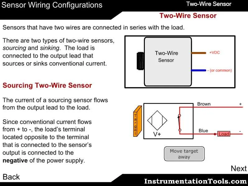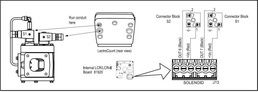
To properly connect a two-terminal control mechanism, ensure that the terminals are correctly aligned to their respective power supply and control circuit. The most common method for this is through a simple on/off switch or direct control from a system’s main relay. One terminal should be connected to the positive side of the circuit, while the other terminal is linked to the negative side, completing the connection for operation.
It is essential to verify that the voltage and current specifications of your control mechanism match the requirements of your power source. A mismatch can lead to malfunction or even damage to the component. For best performance, use appropriate insulation and ensure the connection is secure to prevent any risk of electrical shorts or disconnections during use.
If using a control system, you might need to integrate it with sensors or automated controllers for more complex tasks. In this case, the input signal should be low voltage and should trigger the mechanism’s action without overloading the system. Regular maintenance checks and testing of the connections can prevent operational issues over time.
Connecting a 2-Terminal Electromagnetic Component
For a proper setup of a 2-terminal actuator, follow these steps carefully:
- Power Source: Ensure the power supply is appropriate for the component’s voltage and current requirements.
- Terminal Identification: Typically, the two terminals are marked for easy identification: one for positive and one for negative connection.
- Correct Orientation: Verify the correct orientation of the terminals, as reverse polarity can damage the system or cause malfunction.
- Connection Method: Use high-quality connectors or terminals that match the wire gauge for secure and reliable contact.
Double-check that all connections are tight and insulated to prevent short circuits. Proper grounding of the system can also help prevent electrical interference or hazards.
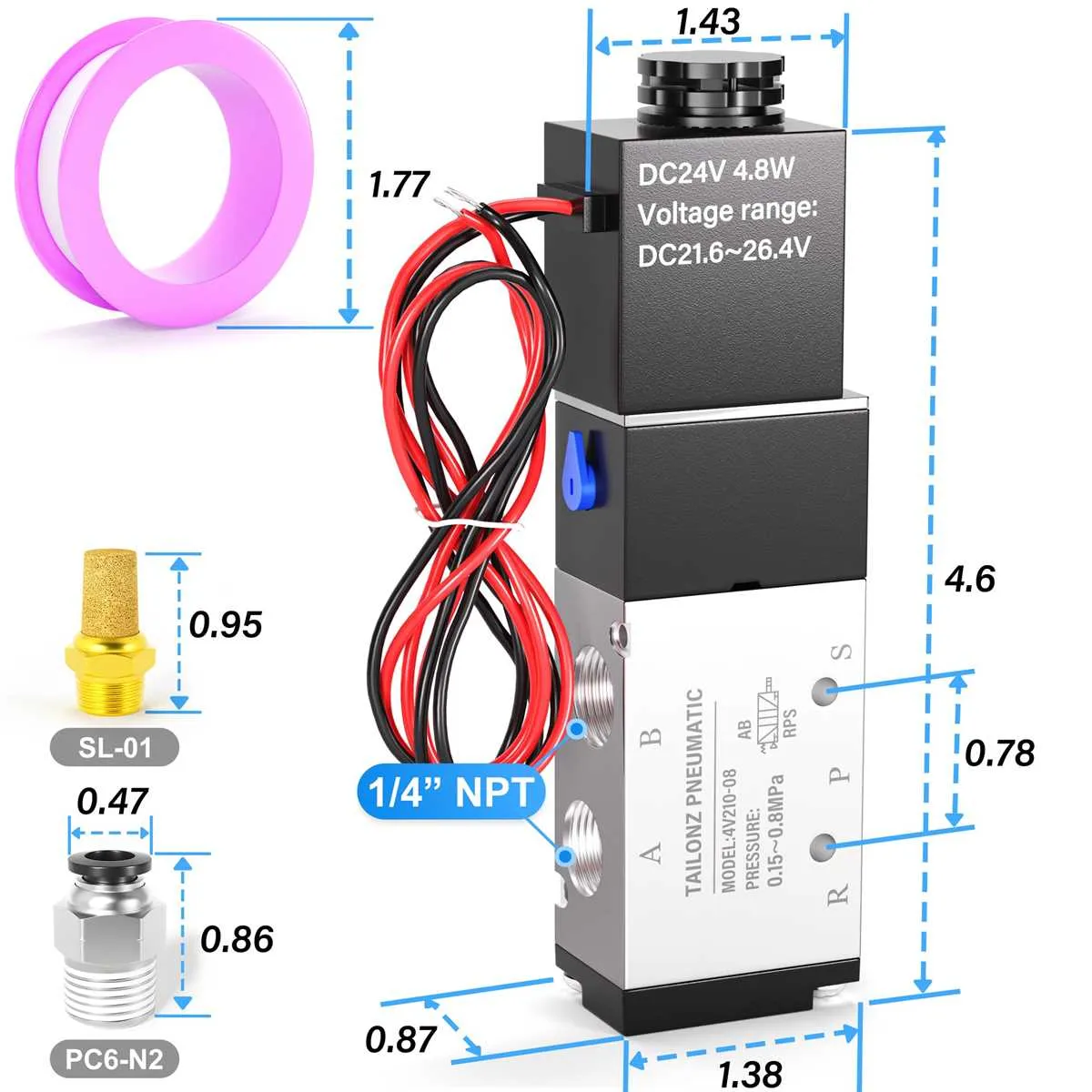
Understanding the Basics of 2 Wire Solenoid Valve Connections

To establish a reliable circuit for a two-terminal actuator, ensure a proper connection between the control unit and the device. For a basic setup, connect the two terminals directly to the power source, respecting polarity. When integrating a DC-operated actuator, a rectifier may be necessary for efficient operation.
Check for correct voltage ratings on both the actuator and the power supply to avoid damaging components. A typical installation requires a direct link to a DC or AC power system, depending on the actuator’s requirements. In some cases, a protection circuit, such as a diode or fuse, is recommended to prevent back-voltage spikes during deactivation.
If you use a control system, such as a PLC or relay, make sure to account for its control signal and make proper connections to maintain seamless operation. A switching element in the control unit can activate or deactivate the device, ensuring optimal performance for various industrial applications.
Also, pay attention to the physical distance between components. If the connection is too long, voltage drops may occur, compromising the functionality. Keep the conductors as short as possible and ensure secure contacts at both terminals for the best results.
Common Mistakes to Avoid in 2-Wire Connection Systems
Ensure proper polarity when connecting the two leads. Reversing the connections can result in malfunction or failure of the system to operate as intended.
Avoid overloading the power supply. Using a power source with insufficient voltage or current can cause damage to the components or prevent proper function. Always check the manufacturer’s specifications for the correct power requirements.
Do not ignore proper insulation. Failing to secure the connections can lead to short circuits or unintended activation. Insulating all exposed metal parts reduces the risk of electrical faults.
Check for ground faults. Improper grounding can cause erratic behavior or even permanent damage to the unit. Always ensure a solid connection to ground.
Incorrect placement of the component can result in physical stress or exposure to elements that can degrade its performance. Install the unit in an appropriate, protected location, following manufacturer guidelines.
Do not bypass safety components or features. Disabling limit switches, overcurrent protection, or other built-in safety features can lead to dangerous operation or void warranties.
Ensure proper connection orientation when inserting components. A misaligned connection can prevent activation or result in partial operation.
Use the correct gauge for connecting leads. A mismatch between the wire thickness and the system’s needs can lead to overheating and potential failure.
How to Troubleshoot Electrical Issues in 2-Wire Valve Control Systems

Check the power supply first. Ensure the voltage matches the device’s requirements. Measure the input voltage using a multimeter to confirm it’s within the specified range. If the voltage is too low, inspect the power source for issues.
Verify the connections at both ends of the device. Loose or corroded connections can disrupt the signal flow. Inspect the terminals and connectors carefully, making sure they are clean and securely attached.
If no power issue is detected, test the continuity of the circuit. Use a multimeter to check for an open circuit between the device’s terminals. If there’s no continuity, the component might be damaged and require replacement.
Check for short circuits by testing the resistance between the two terminals. If the reading is too low or zero, there may be an internal short. This can often be caused by a defective component or improper installation.
Ensure proper grounding. A floating or poor connection to ground can result in erratic performance or failure to operate. Test the ground connection for resistance to verify it’s working correctly.
If everything seems intact but issues persist, test the control signals with a signal tester. A malfunctioning controller or faulty signal may be responsible for the issue. Ensure the signal strength and integrity are within operational specifications.
Lastly, if no faults are found, the problem may lie within the internal components. In such cases, disassemble the device (if possible) to check for visible damage, such as burnt components or physical wear.