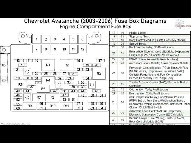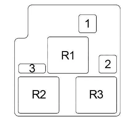
Check under the hood on the driver’s side near the battery. A black plastic cover hides the main power relay hub. Remove the lid to access relays for the starter, fuel pump, cooling fan, and high-output circuits. Labels inside the cover indicate positions, but some abbreviations can be misleading–consult the owner’s manual for decoding.
Inside the cabin, look at the side of the dashboard visible when the driver’s door is open. Behind a small snap-off panel, you’ll find the cabin circuit grid. This contains feeds for the HVAC blower, interior lights, power windows, radio, and instrument cluster. Use a test light to verify voltage and continuity before replacing any mini blade units.
Power outlet issues? Inspect slot 2 in the cabin grid–it typically handles the accessory socket. If non-functional, confirm amperage rating and inspect for corrosion. Replace only with identical low-profile elements to prevent thermal overload.
Heated seat or trailer wiring faults often trace back to the relay center beneath the hood. Double-check ground connections and replace faulty terminals. For towing functions, also verify rear harness integrity near the bumper where moisture ingress is common.
Underhood Relay Layout and Cabin Panel Chart
Start by checking the access panel on the driver’s side dash–visible when the door is open. The top-left slot controls the left-side low beam; labeled as position 1, it uses a 10A micro-type element. Adjacent to it, slot 2 covers the right-side low beam with identical specs. For power windows, inspect slot 19, which is a 30A circuit breaker rather than a blade insert.
Move to the compartment near the battery. Look for the square-shaped relay marked “DRL,” managing daytime lights. It’s beside the HVAC blower relay. To disable DRLs temporarily, remove this unit. The ABS pump control is managed through a 60A maxi type, positioned third from the left on the lower row.
The trailer wiring system relies on two key inserts: a 40A type for the auxiliary circuit and a 30A blade for trailer brake control, located in the right column of the underhood unit. Swapping any component requires matching amp ratings precisely. Never replace with higher values to avoid melting the housing or wire insulation.
Underhood fuse box layout and fuse functions

Check the power distribution unit located near the battery on the driver’s side. Remove the plastic cover to access labeled terminals and relays.
IGN A (10A): Controls ignition coils and engine sensors. If there’s a crank but no start, inspect this circuit.
INJ (15A): Powers the fuel injectors. Engine misfires or rough idling may result from issues here.
ABS (60A): Manages the anti-lock braking module. Warning light on the dash often signals a blown link here.
DRL (15A): Operates daytime running lights. Dim or non-working front lights are signs of a fault.
PCM B (20A): Feeds voltage to the powertrain control module. A no-start condition or shifting problems can point to this connection.
ECM1 (15A): Handles power to the engine control module and fuel pump relay. If the vehicle stalls intermittently, verify this segment.
TRAILER (30A): Supports trailer lighting and electric brakes. Towing-related malfunctions often trace back to this source.
HVAC (30A): Powers climate control blower motor. If there’s no airflow from vents, inspect this slot.
Always disconnect the negative battery terminal before servicing. Use a test light or multimeter to confirm continuity before replacing any component.
Cabin fuse panel location and diagram
Access the interior power module by opening the driver’s side door and removing the cover on the side of the dashboard, just left of the steering column. No tools are required. Use the notched edge to pry the cover off by hand.
This assembly contains relays and miniature blade components controlling interior circuits. Use the label on the rear of the cover as a reference or consult the layout below for detailed mapping.
- 1 – IGN 3: Heated seats, climate control display
- 2 – SEO IGN: Special Equipment Option
- 3 – HVAC 1: Blower motor
- 4 – LDOORS: Driver power windows and locks
- 5 – LOCK: Door locking actuators
- 6 – UNLOCK: Door unlocking actuators
- 7 – STOP: Brake pedal switch
- 8 – CTY LTS: Courtesy lighting
- 9 – INT LTS: Dome lights and map lights
- 10 – RADIO: Audio unit and amplifier
- 11 – ONSTAR: Telematics system
- 12 – HVAC B: Climate control module
- 13 – S/ROOF: Sunroof motor
- 14 – DRV UNLCK: Driver’s door unlock relay
- 15 – DRV LOCK: Driver’s door lock relay
Always verify amperage ratings before replacing any element. Use components matching the original color code and value to avoid circuit damage.
How to identify and replace blown fuses
Start by removing the cover of the electrical panel located under the dashboard or near the engine bay. Use the schematic on the inside of the lid to locate the relevant circuit element by its amperage rating and assigned function.
Pull the suspect component using needle-nose pliers or a dedicated extractor. Hold it up to a light source. A functioning unit has an intact metal strip; a damaged one shows a break or dark discoloration inside the transparent housing.
Check the amperage number stamped on the top (e.g., 10, 15, 20). Always replace with an identical rating to prevent wire damage or fire risk. Insert the new piece firmly into the same slot, ensuring a snug fit. Do not substitute with a higher-rated unit or bypass with wire.
Test the associated system (e.g., power windows, headlights) after installation. If it fails again shortly after replacement, inspect for shorts in the corresponding wiring or malfunctioning devices connected to that circuit.