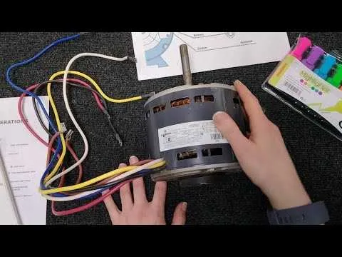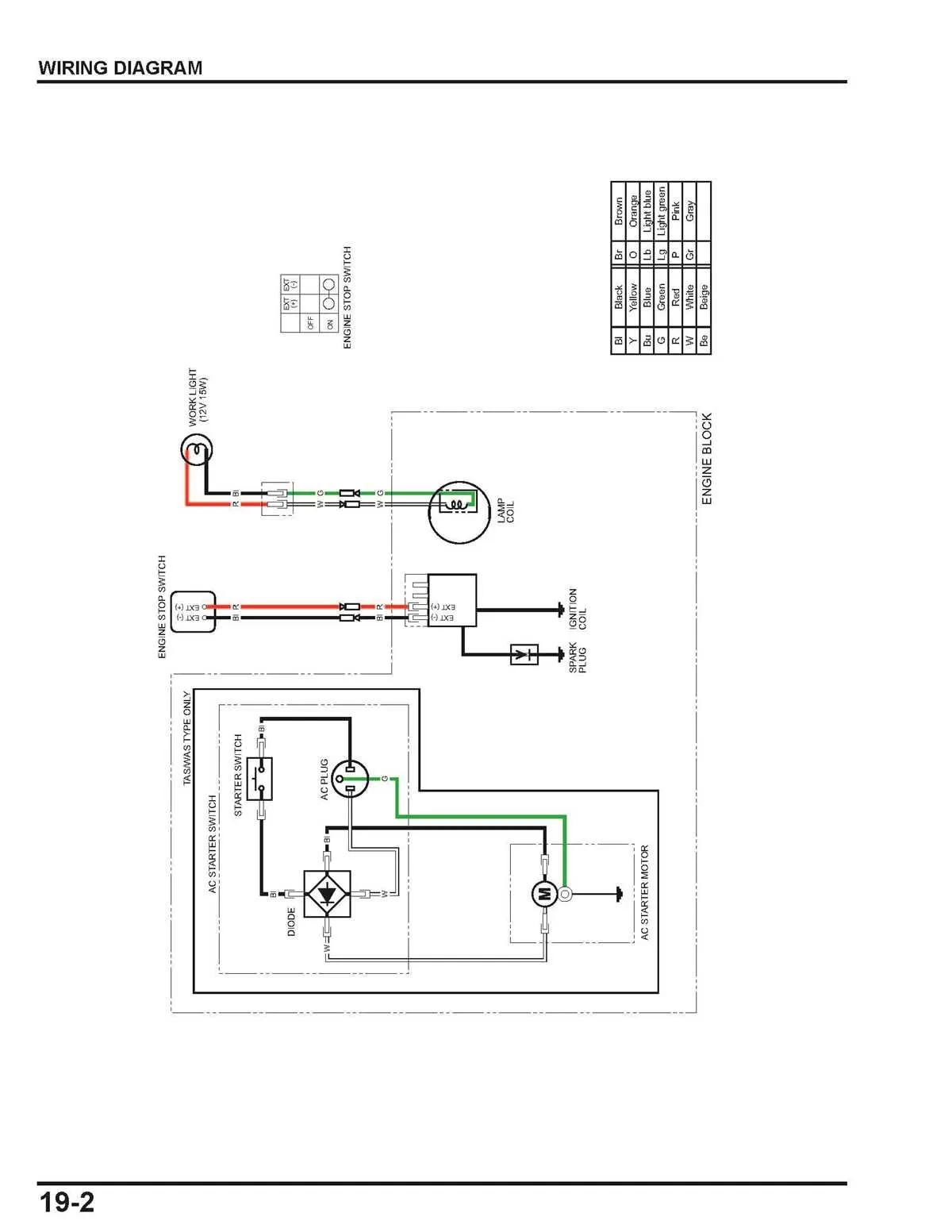
Start by locating the relay unit beneath the dashboard panel, typically positioned adjacent to the HVAC control module. Ensure the ignition is off before proceeding. Identify the color-coded lines: red usually indicates power supply, black is ground, and yellow or green often correspond to signal pathways.
Connector A typically hosts four terminals. Terminal 1 receives input from the climate control switch. Terminal 2 links to the resistor grid, which modulates fan intensity. Terminal 3 is routed to the fuse box for overload protection, and Terminal 4 returns current to the negative pole.
Use a multimeter to verify continuity across terminals. Voltage drop greater than 0.5V may signal corrosion or partial disconnection. When tracing the path to the air distribution module, note any splices or aftermarket additions, as these can distort current flow and introduce failure points.
Inspect thermal fuses integrated within the resistor block. If the fan does not operate at lower speeds, this element is often compromised. Replace only with components rated for matching amperage and temperature thresholds to avoid future short circuits.
Label each route with durable adhesive markers during disassembly. This ensures accurate reassembly and reduces diagnostic time in future maintenance operations.
Blower Motor Wiring Diagram Manual

Begin by disconnecting the negative battery terminal to prevent shorts or injury. Identify the control module connector and locate the output pin responsible for fan speed regulation. Use a multimeter to confirm voltage presence when the system is active. If no signal is detected, trace back to the resistor pack or HVAC control switch.
Inspect all color-coded leads–typically red for power, black for ground, and varying shades like blue or yellow for speed control inputs. Ensure all connectors are fully seated and corrosion-free. For models with an integrated speed controller, verify the pulse-width modulation signal from the ECU using an oscilloscope.
When retrofitting or repairing, match terminal layouts based on manufacturer schematics. Avoid splicing unless using heat-shrink connectors rated for automotive use. If thermal fuses or relays are present in the assembly, test continuity across each with power disconnected.
Always refer to the fuse box diagram under the dashboard or engine bay to locate protection elements linked to airflow management systems. Replace any blown fuses with identical amperage ratings. For vehicles using CAN bus integration, ensure the communication line is intact and not shorted to ground or power.
How to Identify Terminals and Wire Colors
Start by locating the component’s connector block, typically found near the housing or under the dashboard. Use a multimeter to test for continuity and voltage across terminals while referencing color codes.
Common terminal labels include: G (green, usually ground), B+ (red or orange, positive supply), LO/HI (blue, yellow, or white, indicating speed levels), and SIG (often purple or brown, control input). Refer to the unit’s control module for matching identifiers.
Color conventions may vary by manufacturer: for example, Ford often uses orange/black for high speed, while GM may assign purple to low-speed circuits. Trace each lead back to its source or fuse block to confirm its function.
Always disconnect the battery before probing terminals to avoid short circuits. For variable-speed systems, expect a pulse-width modulated (PWM) control line, usually gray or violet, requiring oscilloscope verification.
Steps to Trace and Interpret a Blower Motor Wiring Diagram
Start by locating the terminal legend printed on the inside of the control panel cover or near the control board. Identify all labels such as L1, L2, COM, HI, MED, and LO–these correspond to line voltage, common return, and fan speed taps.
Use a multimeter to verify continuity between leads. Set it to ohms, disconnect power, and test between ground and each color-coded wire. A reading near zero indicates a closed path, confirming internal connections.
Match color codes to speed settings. For example, black often signifies high-speed, blue medium, and red low. Refer to the unit’s key to validate this mapping and ensure proper functionality.
Follow each conductor to its endpoint on the relay, contactor, or capacitor. Trace the route visually and compare it with the printed layout to confirm correct positioning.
Identify the control signal source, typically a thermostat output marked as G or FAN. Confirm whether the circuit completes via a relay coil or direct activation line.
Inspect the capacitor rating and connection type. Ensure the microfarad value matches the nameplate specification and that the common and fan terminals are wired appropriately.
Document your findings with labels or a photo for future reference. Use non-conductive tags or colored tape to mark each lead’s role to avoid miswiring during reassembly.
Troubleshooting Common Fan Assembly Electrical Issues
First, verify power supply continuity and correct voltage at the connector terminals to rule out external electrical faults.
- Inspect connectors for corrosion or burnt contacts that may cause intermittent operation or failure to start.
- Check for broken or frayed cables that could lead to shorts or open circuits, using a multimeter for resistance testing.
- Test the control relay and associated fuses for proper function, replacing any faulty components immediately.
- Ensure ground connections are secure and free from rust or paint that may impede conductivity.
- Measure resistance across the winding coils; abnormal readings often indicate internal damage requiring replacement.
- Look for overheating signs such as melted insulation or discoloration around terminals, which suggest overcurrent issues.
- Confirm the speed control module or resistor pack is operational by comparing output voltages at different speed settings.
Use step-by-step electrical diagnostics to isolate faults efficiently, avoiding unnecessary part swaps.