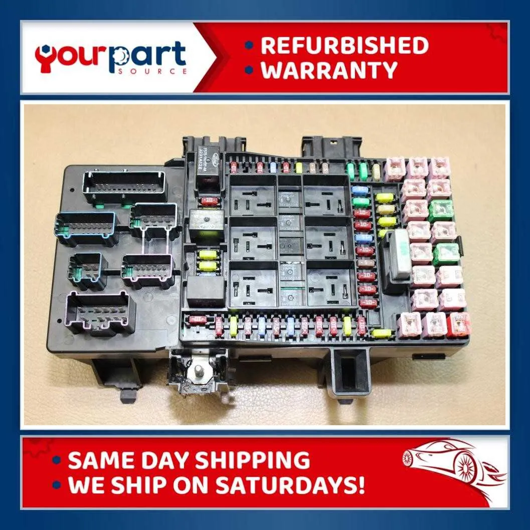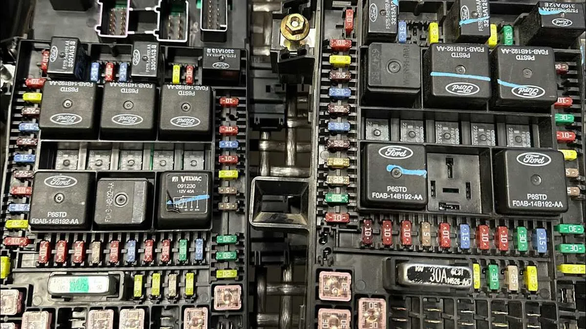
Locate the under-hood power distribution center to identify all circuit protectors crucial for your vehicle’s electrical system. Each holder is clearly numbered and corresponds to specific components such as headlights, ignition, and accessory circuits. Refer to the manufacturer’s schematic to ensure accurate identification of each relay and protective element.
For troubleshooting, always verify the condition of each electrical protector with a multimeter before replacement. Pay particular attention to the main power relay and the ignition switch circuit protection, as failures here often cause starting issues or intermittent power loss. Use a high-quality replacement unit matching the original amperage ratings to maintain system integrity.
Inspect the passenger compartment’s protective panel located beneath the dashboard for auxiliary circuits. This section manages lower-voltage systems, including interior lighting, audio components, and climate control. Proper understanding of this layout is essential for safe maintenance and effective troubleshooting of cabin electronics.
2004 Expedition Fuse Box Diagram
Locate the primary electrical panel under the dashboard on the driver’s side for quick access. Each circuit protector is clearly labeled with amperage ratings ranging from 5A to 30A, designed to safeguard components such as headlights, ignition system, and power windows. Refer to the vehicle manual for exact slot assignments, but typical configurations include a 15A fuse for the horn, 20A for the rear defroster, and 25A for the cooling fan relay.
When replacing any circuit safeguard, ensure the replacement matches the specified rating to prevent electrical faults. Use a test light or multimeter to verify continuity before installation. The secondary junction panel in the engine compartment handles higher amperage links, including those for the ABS module and fuel pump; these are usually protected by fusible links rather than traditional circuit breakers.
For troubleshooting intermittent power losses, inspect connectors for corrosion and ensure the ground connections are secure. Always disconnect the battery before servicing to avoid shorts. If upgrading or adding accessories, consider using an inline fuse holder connected directly to the battery to maintain factory circuit integrity.
Locating and Identifying Fuses in the 2004 Expedition Fuse Box

Access the main power distribution panel under the hood on the driver’s side. The cover is secured by clips–remove it to reveal the internal layout. Each protective element is labeled with a code matching the included schematic on the underside of the lid.
Identify the critical circuits by referencing the printed legend: for example, the ignition system is typically marked as “IGN,” while lighting controls appear as “LTG.” Use a fuse tester or multimeter to check continuity, focusing first on components that fail to operate.
Look for amperage ratings embossed on each insert, commonly ranging from 5A to 30A, to ensure replacements match specifications exactly. Avoid substitutions that deviate from the original values to prevent electrical damage.
For interior power supplies, consult the secondary panel located beneath the dashboard on the passenger side. It contains smaller protective elements governing auxiliary functions such as the radio and power windows.
When identifying a blown element, a visible break in the metal filament or discoloration inside the translucent casing confirms failure. Replace immediately to restore full electrical functionality without risking further issues.
Step-by-Step Guide to Replacing a Blown Fuse in the 2004 Expedition
Locate the panel cover under the hood or inside the cabin, depending on the circuit affected. Use the owner’s manual or a service guide to identify the exact compartment housing the electrical protection components.
Disconnect the negative terminal of the battery to avoid accidental short circuits while working with the electrical system.
Remove the protective lid by unclipping or unscrewing it carefully. Inside, find the legend or map printed on the underside of the cover or in the manual to pinpoint the specific component responsible for the malfunction.
Identify the faulty cartridge by visual inspection; a melted filament or discoloration indicates a failure. Use a test light or multimeter set to continuity mode for precise verification.
Extract the damaged element with a fuse puller tool or needle-nose pliers, ensuring not to damage surrounding parts or connectors.
Replace it with an identical component matching the exact amperage rating, voltage, and size. Installing a different rating risks electrical damage or fire hazards.
Reinstall the protective cover and ensure it is securely fastened to prevent moisture or debris intrusion.
Reconnect the battery terminal and test the affected system for proper operation. If issues persist, verify other circuits or seek professional diagnostics.
Troubleshooting Common Electrical Issues Using the 2004 Expedition Fuse Box Diagram
Start by identifying the exact location of the malfunctioning circuit in the vehicle’s electrical control panel. Follow these steps to isolate and resolve typical power distribution problems:
- Locate the relevant relay or circuit protector: Consult the schematic for the specific position of the protective element linked to the affected system (e.g., headlights, radio, power windows).
- Inspect for visible damage: Remove the protective element and check for melted contacts, discoloration, or broken internal filaments.
- Test continuity: Use a multimeter on the electrical cartridge to verify if the internal conductor is intact. No continuity indicates replacement is necessary.
- Check the power source: Verify voltage presence at the input terminal using a voltmeter to ensure the supply is not interrupted upstream.
- Review grounding points: Confirm that grounding connections are clean, tight, and free of corrosion, as poor grounding can mimic circuit failures.
- Replace with exact specification parts: Use protective components matching the amperage and size detailed in the vehicle’s electrical layout to avoid overloading and potential damage.
- Reassess the affected system operation: After replacement, activate the system to confirm restored function. If the issue persists, inspect wiring harnesses and connectors for shorts or breaks.
Proper use of the schematic expedites pinpointing defective elements, reduces diagnostic time, and ensures reliable repair of power distribution faults.