
If you own a 2007 Mini Cooper, it’s essential to have a thorough understanding of its wiring system. Wiring diagrams play a crucial role in diagnosing and troubleshooting various electrical issues that may arise in your vehicle. Whether you’re a DIY enthusiast or a mechanic, having access to a detailed wiring diagram can make your job much easier.
In this article, we will provide you with a comprehensive guide to the 2007 Mini Cooper wiring diagram. We will explore the various components of the vehicle’s electrical system, including the battery, alternator, starter, lights, and more. By understanding how the wiring is structured, you’ll be able to identify potential problems and effectively resolve them.
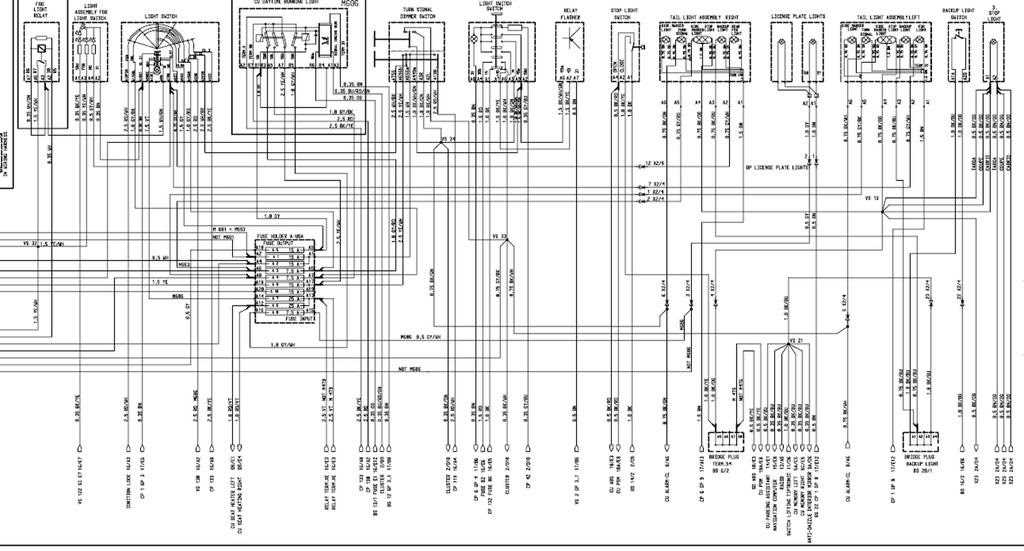
The wiring diagram for the 2007 Mini Cooper contains detailed information about the color codes, connectors, and locations of each wire. This diagram acts as a roadmap that guides you through the electrical system, making it easier to identify specific wires and their corresponding functions. Whether you need to locate a particular wire or troubleshoot a malfunctioning component, the wiring diagram will provide you with the necessary information.
By familiarizing yourself with the 2007 Mini Cooper wiring diagram, you can save yourself time and money on repairs and maintenance. Whether you’re installing an aftermarket stereo system, troubleshooting a faulty light, or replacing a worn-out connector, having a comprehensive wiring diagram at your disposal will make the task much smoother. So, let’s dive into the intricate world of the 2007 Mini Cooper’s wiring system and unlock its secrets!
How to Read and Understand a 2007 Mini Cooper Wiring Diagram
Reading and understanding a wiring diagram is essential for anyone working on electrical systems in a vehicle. In the case of a 2007 Mini Cooper, having a clear understanding of the wiring diagram can help in diagnosing and troubleshooting electrical issues accurately and efficiently.
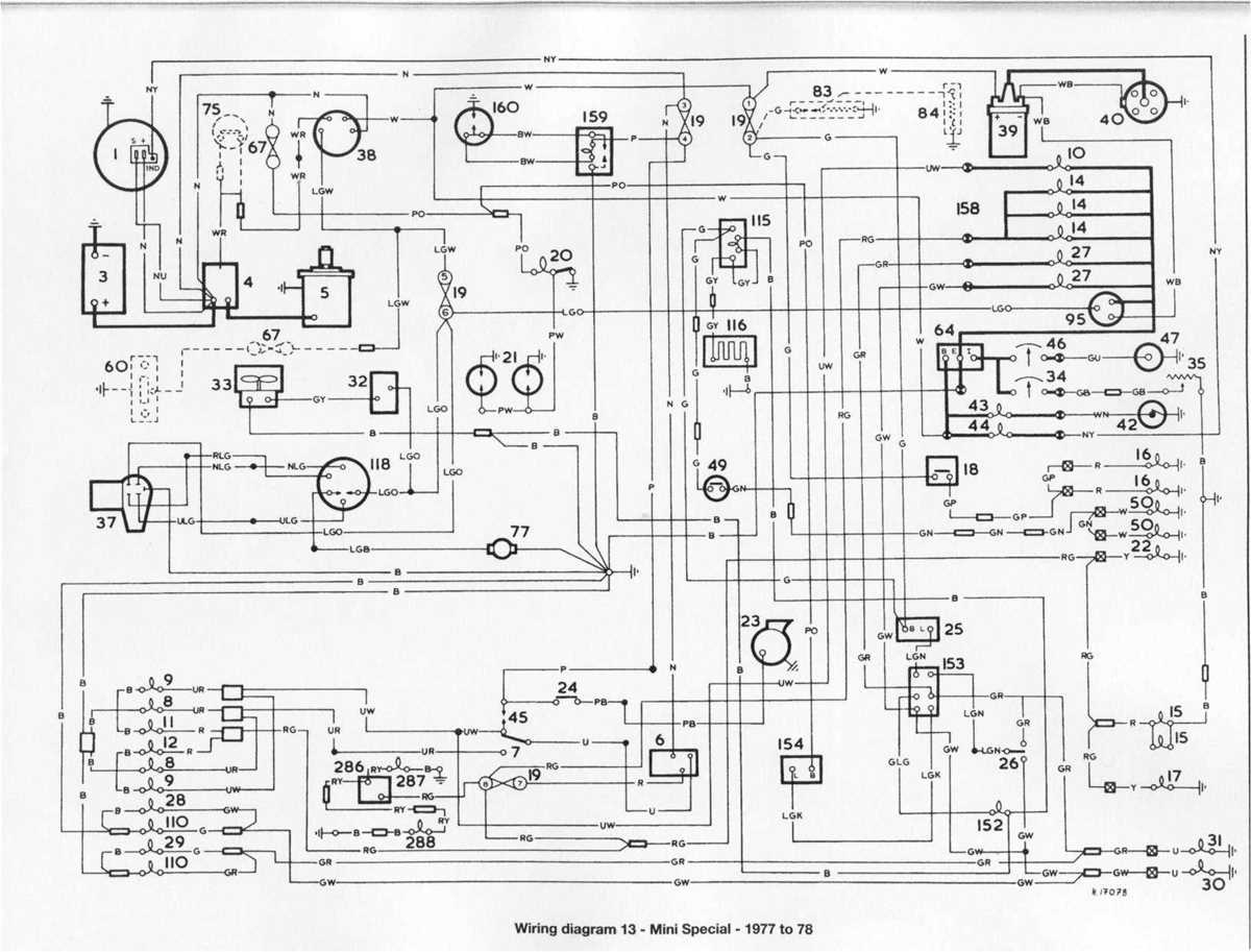
A wiring diagram for a 2007 Mini Cooper is a visual representation of the electrical system in the vehicle. It uses symbols and lines to depict the various components and connections within the system. The diagram helps to illustrate how electricity flows through the different circuits, allowing technicians to identify potential problem areas and locate specific components.
Familiarize yourself with the symbols:
- Lines: Lines represent wires and show the paths that electrical current flows through. Different line styles may indicate different types of wires, such as battery power or ground.
- Symbols: Symbols are used to represent various electrical components, such as batteries, resistors, switches, and sensors. Each symbol has a specific meaning and function within the circuit.
- Numbers and letters: These are used to label specific components or connections. Paying close attention to these labels can help identify the correct part or location within the system.
Once you have familiarized yourself with the symbols and labels, you can start analyzing the wiring diagram by following the flow of electricity through the different circuits. Start at the power source, such as the battery or fuse box, and trace the path through each component and connection until you reach the desired destination or component.
It is important to have a good understanding of the vehicle’s overall electrical system and how the different components work together. This will help in understanding the purpose and function of each wire and connection depicted in the wiring diagram.
Use color coding:
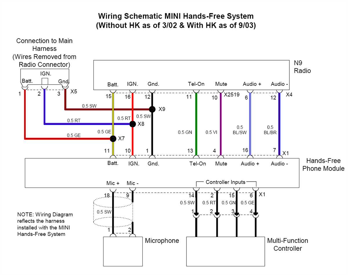
Color coding can be a helpful tool when reading a wiring diagram. In the case of a 2007 Mini Cooper, wires may be color-coded to indicate their specific function or purpose. For example, red wires may indicate power or positive connections, while black wires may indicate ground or negative connections. Be sure to refer to the key or legend provided in the wiring diagram to understand the color coding scheme.
By following these steps and taking the time to study and understand the wiring diagram, you can gain valuable insights into the electrical system of a 2007 Mini Cooper. This knowledge will enable you to effectively troubleshoot and repair any electrical issues that may arise, ensuring the proper functioning of the vehicle’s electrical system.
Why You Need a Wiring Diagram for Your 2007 Mini Cooper
When it comes to troubleshooting electrical issues or making modifications in your 2007 Mini Cooper, having a wiring diagram is essential. This diagram is a detailed visual representation of the electrical system in your car, showing the connections between all the electrical components. It provides valuable information on how the system is organized and how each component is wired, allowing you to understand and navigate the complex network of wires in your car.
Identifying and fixing electrical problems: With a wiring diagram, you can easily identify and locate specific wires and electrical components in your Mini Cooper. This can be especially helpful when dealing with issues such as blown fuses, malfunctioning switches, or faulty wiring connections. By following the diagram, you can determine which wires are responsible for a particular function, and trace them to locate any potential problems.
Modifying or adding new features: If you’re planning to customize your 2007 Mini Cooper or add new features like aftermarket stereo systems or lighting upgrades, having a wiring diagram is crucial. It allows you to understand how the existing electrical system is structured, so you can safely integrate your modifications without causing any damage or electrical problems. By following the diagram, you can easily identify the appropriate connection points and ensure that your new components are correctly wired into the system.
Ensuring safety and preventing damage: Working with the electrical system of any vehicle can be dangerous, as improper wiring can cause short circuits, fires, or damage to sensitive electronics. By having a wiring diagram, you can follow the proper wiring guidelines and ensure that all connections are made correctly. This will help prevent accidents and expensive damages, ensuring the safety and reliability of your 2007 Mini Cooper.
In conclusion,
Having a wiring diagram for your 2007 Mini Cooper is essential for identifying, troubleshooting, and modifying the electrical system in your car. It provides a visual representation of the wiring connections, helping you locate and fix electrical problems, as well as safely integrate any modifications you may want to make. By following the wiring diagram, you can ensure the safety and reliability of your car’s electrical system, preventing damage and potential accidents.
Key Components and Connections in the Wiring Diagram
In the 2007 Mini Cooper wiring diagram, there are several key components and connections that play an important role in the electrical system of the vehicle. Understanding these components and connections can help in diagnosing and troubleshooting any issues with the wiring.
Main components:
- Battery: The battery is the main power source for the electrical system. It provides the necessary voltage for all the electrical components in the vehicle.
- Alternator: The alternator is responsible for charging the battery while the engine is running. It converts the mechanical energy from the engine into electrical energy to keep the battery charged.
- Fuse box: The fuse box contains fuses that protect the electrical system from overloads. Each fuse is designated to a specific circuit and will blow if there is an electrical overload, preventing damage to the components.
Connections:
- Ground connections: Ground connections are crucial for the proper functioning of the electrical system. They provide a path for electrical current to return to the battery. It’s important to ensure that all ground connections are clean and tight to maintain a good electrical connection.
- Connector terminals: Connector terminals are used to make connections between different components. They are typically plug-and-play connectors that provide a secure and reliable connection. Checking and cleaning these terminals can help resolve any connectivity issues.
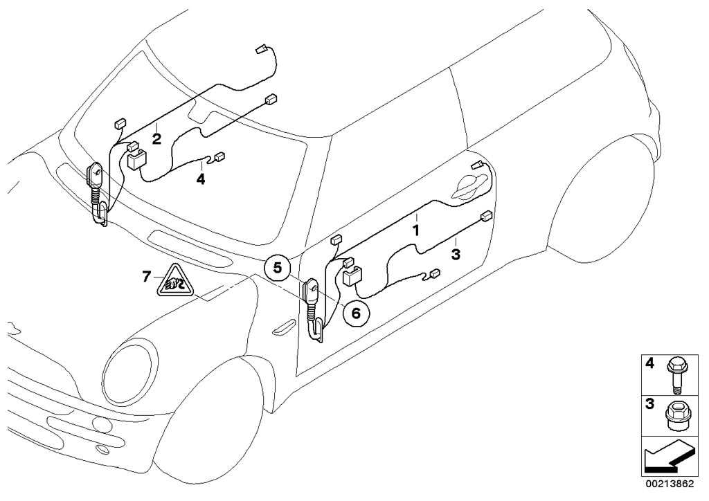
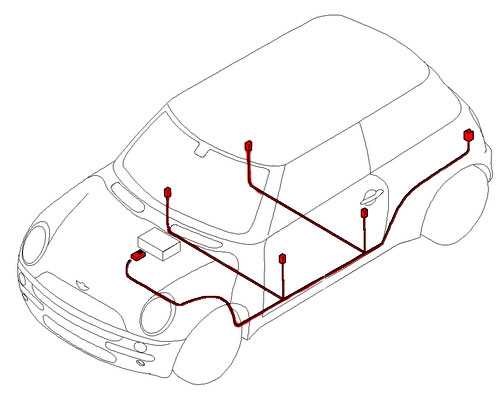
- Wiring harness: The wiring harness is a bundle of wires that connects all the electrical components in the vehicle. It provides a neat and organized way to distribute power and signals. Any damage or breakage in the wiring harness can cause electrical problems and should be repaired or replaced.
By understanding the key components and connections in the wiring diagram, it becomes easier to identify and resolve any electrical issues in the 2007 Mini Cooper. Proper maintenance and regular inspection of these components can help ensure the smooth operation of the vehicle’s electrical system.
Interpreting the Color Codes and Symbols in the Diagram
When looking at a wiring diagram for a 2007 Mini Cooper, it’s important to understand the meaning behind the various color codes and symbols used throughout the diagram. These codes and symbols are used to represent different electrical components, connections, and actions within the vehicle’s electrical system.
One of the key aspects of interpreting the wiring diagram is understanding the color codes for the wires. Each wire is assigned a specific color to indicate its purpose and function. For example, a red wire may be used to indicate power supply, while a black wire may represent ground or earth connection. By referring to the color codes, you can easily identify which wires are responsible for specific functions.
In addition to the color codes, symbols are also used in the wiring diagram to represent various components and connections. These symbols provide a visual representation of the different electrical elements in the system. Some common symbols you may come across include a straight line for a wire, a circle for a connector, and various shapes to represent different electrical components like resistors, capacitors, and switches. By understanding these symbols, you can easily identify which components are involved in a particular circuit.
Key Color Codes
- Red: Power supply
- Black: Ground or earth connection
- Yellow: Ignition switch or accessory power
- Green: Signal or sensor input
- Blue: Control or output signal
Common Symbols
- Straight Line: Represents a wire or conductor
- Circle: Represents a connector or terminal
- Resistor: Represents a component that resists the flow of electrical current
- Capacitor: Represents a component that stores and releases electrical energy
- Switch: Represents a component that opens or closes an electrical circuit
By familiarizing yourself with the color codes and symbols used in the wiring diagram, you will be able to easily navigate and understand the electrical system of your 2007 Mini Cooper. This knowledge can be invaluable when troubleshooting electrical issues or making modifications to the vehicle’s electrical system.
Troubleshooting Common Electrical Issues with Your Mini Cooper
Mini Cooper is known for its compact size and stylish design, but like any vehicle, it can experience electrical issues over time. If you’re having problems with the electrical system in your 2007 Mini Cooper, it’s important to troubleshoot the issues to get them resolved quickly and avoid any further damage.
1. Battery Problems: One of the most common electrical issues in any car is a faulty battery. If your Mini Cooper is experiencing problems starting or the lights are dim, it may be a sign that the battery needs to be replaced. Check the battery connections for any corrosion or loose cables. If necessary, have the battery tested to ensure it’s holding a charge.
2. Blown Fuses: If certain electrical components in your Mini Cooper, such as the radio or power windows, are not working, it may be due to a blown fuse. Check the fuse box, located in the engine compartment or under the dashboard, and replace any blown fuses with the appropriate amperage rating. Be sure to consult the owner’s manual for the correct fuse specifications.
3. Faulty Wiring: Another common electrical issue in Mini Coopers is faulty wiring. Over time, the wiring can become frayed or damaged, leading to various electrical problems. Inspect the wiring harnesses and connectors for any signs of wear or damage. If necessary, repair or replace the faulty wiring to restore proper electrical function.
4. Malfunctioning Alternator: The alternator is responsible for charging the battery while the engine is running. If your Mini Cooper’s battery is constantly draining, it may be a sign of a malfunctioning alternator. Check the alternator’s electrical connections and test its output using a multimeter. If the alternator is not functioning properly, it will need to be replaced to prevent further electrical issues.
By addressing these common electrical issues and following proper troubleshooting steps, you can keep your 2007 Mini Cooper running smoothly and avoid any costly repairs. If you’re unsure about how to fix an electrical problem, it’s always best to consult a professional mechanic or an authorized Mini Cooper dealer for assistance.
Tips for Using the Wiring Diagram to Install or Repair Components
When using the wiring diagram to install or repair components in a 2007 Mini Cooper, there are several tips to keep in mind to ensure a successful and efficient process. Here are some key points to consider:
- Familiarize yourself with the diagram structure: Before starting any installation or repair work, take the time to study and understand the wiring diagram. Pay attention to the layout, symbols, and color codes used to represent different components and electrical connections.
- Use proper safety precautions: Working with electrical systems can be dangerous, so it’s essential to follow safety guidelines. Make sure to disconnect the battery before starting any work and use appropriate protective gear, such as insulated gloves and goggles, to prevent electrical shocks.
- Double-check connections: When installing or repairing components, double-check all connections to ensure they are properly seated and secure. Loose or faulty connections can lead to electrical malfunctions and potential damage to the vehicle.
- Follow the wiring diagram step-by-step: The wiring diagram provides a detailed sequence of steps to follow for component installation or repair. It’s important to adhere to this sequence to avoid confusion and ensure that all necessary connections are made correctly.
- Refer to additional resources if needed: If you encounter any difficulties or have questions while using the wiring diagram, consult other resources such as repair manuals or seek assistance from experienced professionals. Don’t hesitate to ask for help to prevent mistakes or accidents.
In conclusion, using the wiring diagram as a guide for installing or repairing components in a 2007 Mini Cooper requires careful attention to detail, adherence to safety precautions, and a thorough understanding of the diagram’s structure. By following these tips, you can ensure a successful and accurate installation or repair process.
Q&A:
What is a wiring diagram?
A wiring diagram is a visual representation of the electrical connections and wiring layout of a system or component.
Why is a wiring diagram important when installing or repairing components?
A wiring diagram is important as it provides a guide on how the electrical connections should be made, helping to ensure that the components are correctly installed or repaired.
How can a wiring diagram be used to install components?
A wiring diagram can be used to identify the correct wires and their respective connections, making it easier to install the components in the right sequence.
How can a wiring diagram be used to repair components?
A wiring diagram can be used to identify the faulty connections or components, aiding in the troubleshooting and repair process.
What are some tips for using a wiring diagram effectively?
– Carefully study the diagram and understand the symbols and connections
– Use appropriate tools and safety measures
– Verify the accuracy of the diagram with the actual wiring
– Follow the sequence of connections as shown in the diagram
– Double-check the connections before applying power