To quickly resolve issues with interior lighting, window controls, or the audio system, inspect the passenger-side relay center beneath the dashboard. Remove the panel by gently pulling it outward to reveal labeled circuits responsible for cabin electronics. A blown component here can disable power mirrors or central locking.
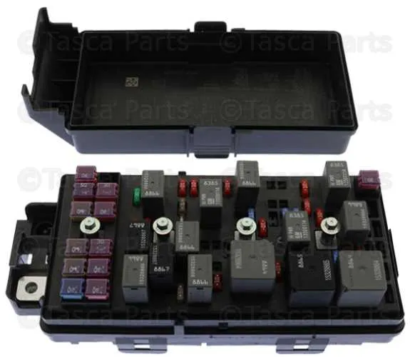
For engine-related concerns such as starter failure or cooling fan inactivity, access the underhood control unit near the driver-side strut tower. This assembly manages high-load elements including the ignition module and fuel pump relay. Use a test light or multimeter to check continuity across terminals before replacement.
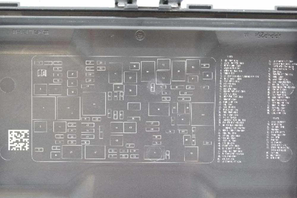
Label identifiers inside each housing cover provide critical guidance. These references use abbreviations like IGN, ACCL, or RAD to designate specific roles. Replacements should match amperage ratings exactly; overrating can cause wire overheating, while underrating leads to nuisance tripping.
Routine inspection and keeping spare mini-blades in the glove compartment prevent avoidable roadside issues. Always disconnect the negative battery terminal before handling any electrical elements to avoid short circuits or personal injury.
Main Panel Layout and Slot Assignments

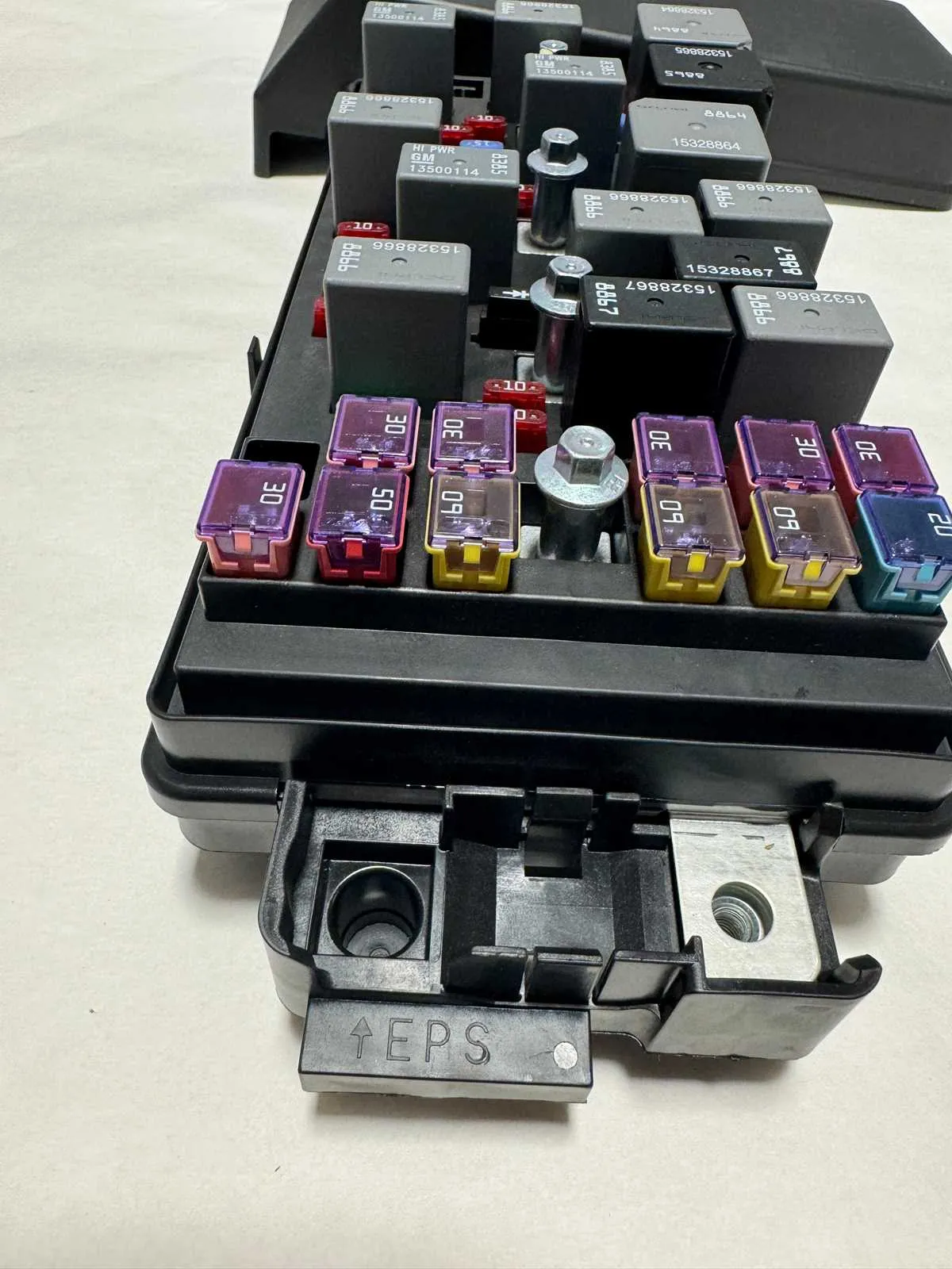
Locate the primary enclosure under the hood, near the driver’s side strut tower. Remove the cover by pressing the side clips. Inside, a layout guide shows component positions.
Key positions include:
- Slot 15 – Cooling fan relay
- Slot 26 – Starter solenoid control
- Slot 36 – ABS module supply
- Slot 47 – Ignition coils
- Micro Relay 39 – A/C compressor clutch
Interior unit access: Open the driver-side door and remove the side panel of the dashboard. Refer to the label behind the cover for module identification.
Interior slots to note:
- Position 2 – Power windows
- Position 9 – Instrument cluster
- Position 15 – Radio and infotainment
- Position 20 – Brake lights
Always disconnect the negative terminal before replacing any component. Use only rated replacements as indicated in the owner’s chart.
Interior Fuse Box Location and Access Instructions
Start by opening the driver’s side door fully to gain clear access to the left edge of the dashboard. Look for a rectangular cover panel facing the door – it sits flush with the dash surface and includes a small notch at the bottom for prying.
Use a flat-head screwdriver or your fingers to carefully pull the panel outward. Behind it, you’ll find a labeled grid identifying each electrical component protected in this section.
If needed, refer to the layout chart printed on the back of the cover for slot identification. Ensure the ignition is off before attempting any checks or replacements. When done, align the panel with its mount points and press it back into place until it clicks securely.
Fuse Assignments for Underhood Fuse Block with Component Functions

Check the under-hood relay center when diagnosing power distribution issues. Below is the allocation list with key systems and corresponding amperages:
- ECM/TCM (15A): Controls engine and transmission modules.
- Cooling Fan Relay (40A): Activates radiator fan to regulate engine temperature.
- Starter Relay (30A): Powers the starter solenoid during ignition.
- ABS Pump (60A): Supplies energy to the anti-lock braking hydraulic motor.
- Air Conditioning Clutch (10A): Engages compressor clutch for climate control.
- Ignition Coil Feed (15A): Provides voltage to coil packs.
- Oxygen Sensor Heater (10A): Ensures rapid warm-up of emission sensors.
- Fuel Pump Relay (20A): Delivers current to the fuel delivery system.
- Transmission Solenoids (15A): Operate hydraulic actuators for gear changes.
- Electric Power Steering (30A): Drives assist motor for steering input.
Use a multimeter or test light to verify current flow across terminals. Replace any faulty element only with a unit of matching rating to avoid circuit damage.
How to Identify and Replace a Blown Fuse in the 2010 Malibu
Locate the power distribution panel under the dashboard or in the engine compartment. Use the vehicle’s manual or the label on the panel cover to find the specific component associated with the malfunctioning system.
Inspect each element for a visible break or dark discoloration in the metal strip inside. A damaged connector indicates a failed circuit protector that needs replacement.
Before removal, disconnect the ignition and electrical load to avoid shorts. Use a fuse puller or needle-nose pliers to carefully extract the faulty part from its slot.
Match the replacement unit’s amperage rating precisely to the original to maintain proper circuit protection. Insert the new piece firmly into the correct location until it clicks or is secure.
After installation, test the affected electrical component to confirm restoration of function. If the new device blows immediately, further electrical diagnosis is required to identify underlying issues.