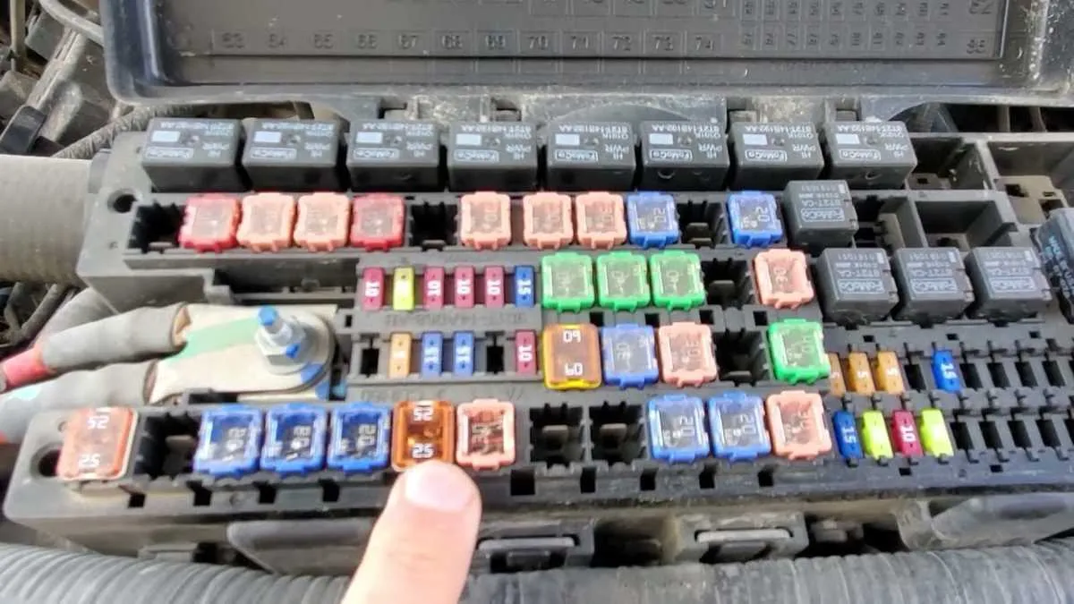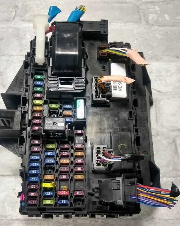
To troubleshoot electrical components in the engine compartment, start by identifying the precise layout of the power distribution unit. It houses several relays and circuit protection devices that control essential functions like lights, ignition, and cooling systems. The configuration includes multiple rows of fuses, each dedicated to specific circuits within the vehicle’s powertrain system.
Key areas to focus on: Pay attention to the main relay cluster, which manages critical connections for engine management. Identifying the location of each fuse can save significant time during diagnostics. Some circuits are dedicated to high-demand components, while others regulate auxiliary systems, such as the air conditioning or fuel injection control.
When performing checks, ensure that each relay and fuse is properly seated in its respective slot. Cross-referencing the diagram with the vehicle’s user manual helps in pinpointing the exact components and prevents any confusion during replacement or repair. Always double-check the amperage ratings to avoid overloading circuits and causing further damage to the electrical system.
Electrical Component Layout and Fuse Allocation
The main relay panel located in the engine compartment houses the critical electrical connections for several systems. Ensure that the connections are checked periodically for any signs of wear or corrosion, which could affect vehicle performance.
Top left section: The first set of terminals controls systems such as the cooling fan and the air conditioning unit. If there is an issue with these components, check the corresponding connections for damage or blown relays.
Central area: This section provides power to components like the fuel injectors and ignition system. Faulty connections here may cause starting problems or misfires, so always confirm the integrity of the wiring when diagnosing such issues.
Bottom-right section: Handles accessories such as windshield wipers and power windows. A blown relay in this area may result in inoperative features, often indicating an issue with high-current systems.
In all cases, refer to the detailed terminal numbers and follow the specific maintenance instructions for each relay or fuse. Never replace a relay or fuse without confirming the amperage rating, as using an incorrect component can cause severe damage to the electrical system.
Identifying the Main Fuse Box Location and Components
Locate the primary electrical distribution unit in the engine compartment, typically near the driver’s side. It is positioned adjacent to the battery, often secured with clips or latches for easy access. This unit contains various relays, fuses, and connectors that control critical systems such as the ignition, cooling fans, and lighting circuits.
Common components within this unit include a set of high-power fuses for the engine and essential accessories, as well as smaller fuses that protect individual circuits like the headlights or HVAC system. The diagram inside the cover provides clear labeling for each fuse’s function, ensuring straightforward identification of components when troubleshooting or performing maintenance.
Ensure the electrical unit is securely closed after maintenance to avoid exposure to environmental elements that could cause rust or corrosion over time. Always disconnect the battery before working within the compartment to avoid electrical shock or short circuits.
How to Troubleshoot Common Electrical Issues in a 2012 Pickup
If your vehicle’s electrical components stop working, the first step is to check the relay and wiring circuits for any visible damage. Look for signs of corrosion, frayed wires, or burnt connections that could affect power flow.
1. Inspect the Main Power Distribution
Start by verifying the connection points for any signs of melting, discoloration, or burnt marks. Any of these could indicate a serious issue with power distribution. Make sure all fuses are properly seated and have not been tripped or blown.
2. Check Specific Circuits
If particular components aren’t functioning, check their corresponding power pathways. For instance, if the lights or radio aren’t working, trace their circuit to ensure there are no obstructions or breakages along the wiring.
3. Test Relays and Connectors
Relays often control various systems in the truck, and they can wear out over time. Use a multimeter to check relay functionality by testing for continuity or switching them with known good ones to see if the issue is resolved.
4. Replace Damaged Components
If you find broken or burnt elements, replace them with the correct type and rating. Never use a fuse or relay that is not suited for your vehicle’s specifications as it could lead to further damage or even fire hazards.
5. Verify Grounding
Improper or loose grounding can cause electrical failures. Check all grounding points to ensure they’re clean, tight, and free from rust or dirt. A poor connection can lead to intermittent or complete power loss.
Step-by-Step Guide to Replacing Fuses in the Engine Compartment Electrical Panel

To replace faulty components in the engine compartment’s electrical panel, follow these steps carefully:
- Turn off the vehicle’s ignition and remove the key.
- Locate the electrical panel in the engine compartment. This is usually found near the driver’s side, next to the battery.
- Open the panel cover. Depending on your vehicle, you may need to unlatch or unscrew the cover.
- Identify the blown component by inspecting the transparent covers. You’ll usually find the details of the components listed on the back of the cover or inside the manual.
- Use a fuse puller or a pair of needle-nose pliers to remove the damaged element. Be cautious not to damage the surrounding components.
- Check the amperage rating of the removed item. Ensure the replacement matches the exact rating (this info can be found in your vehicle’s manual or on the fuse itself).
- Insert the new component into the appropriate slot, ensuring it fits snugly and securely.
- Close the panel cover and ensure it’s securely latched.
- Turn on the ignition and check that the electrical function linked to the replaced item is working properly.
In case the same problem occurs frequently, consider inspecting the wiring or consulting a professional mechanic to rule out deeper electrical issues.