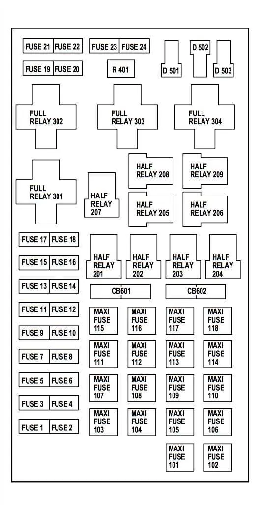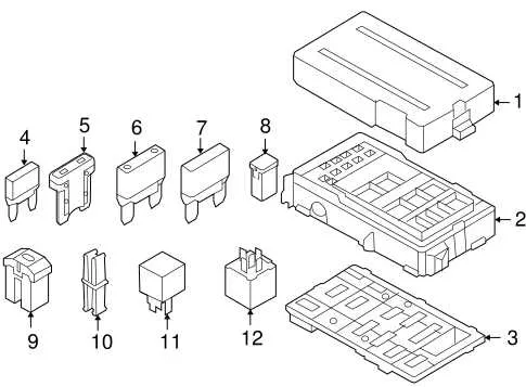
If you’re troubleshooting or replacing any electrical components, knowing the precise location and function of each circuit is essential. For your truck model, refer to the schematic that maps the various relays and connections, ensuring proper diagnostics and effective repairs. Whether you’re dealing with power windows, lights, or any other features, following the correct layout will streamline the process and prevent accidental damage.
To ensure safety when working on the electrical system, always disconnect the main power source before performing any repairs. Locate the main terminals and ensure all connections are free from corrosion and securely fastened. The detailed chart will help you identify the corresponding slots for each circuit, from high-amperage connections to smaller control systems.
For any unexpected issues or blown circuits, use a multimeter to verify each connection’s functionality. Pay close attention to each individual relay’s rated capacity and avoid overloading circuits. Following the manufacturer’s guide on amperage limits and component protection is crucial for maintaining the longevity of the electrical system.
Having the correct reference in hand can save you time and effort when troubleshooting electrical faults. The organized layout helps you pinpoint any malfunctioning sections or components, enabling swift and efficient resolution of any electrical issues.
Electrical System Layout and Component Guide
For proper functionality of your vehicle’s electrical circuits, refer to the layout that outlines the placement and identification of critical relays and electrical components. The main panel, located on the driver’s side of the cabin beneath the dashboard, houses essential connections that manage power distribution across various systems, including lights, climate control, and security features. A secondary unit under the hood supports higher power circuits for the engine and transmission systems.
To identify malfunctioning areas, start by checking the smaller, interior unit. This section handles accessories, including audio, HVAC, and interior lighting. For any issue related to external lighting or powertrain, shift your focus to the external compartment. Always ensure that each connection is secure, as loose or corroded terminals can cause intermittent failures.
If a specific electrical feature is not functioning, consult the corresponding section of the manual to locate the relevant relay or circuit breaker. Each unit is clearly labeled to assist with troubleshooting. When replacing or resetting a component, it is crucial to power off the vehicle completely to avoid damage or short circuits.
For optimal maintenance, regularly inspect for any visible signs of wear or corrosion around the terminals. Preventive checks can extend the longevity of your vehicle’s electrical systems and ensure smooth operation.
Understanding the Location and Layout of the Electrical Component Housings in the 2013 Ford F150

The primary units for managing electrical connections in this vehicle are situated in two main areas: the engine compartment and the cabin. Proper identification and understanding of their placement will ensure easy access for maintenance and repairs.
- Under the Hood: In the engine compartment, you’ll find a large unit near the driver’s side. This is the main control for most of the high-power systems, including the alternator and battery. It’s essential to check this housing for any blown components that may affect engine performance.
- Inside the Cabin: There’s another compartment located under the dashboard on the driver’s side, near the lower part of the dash. It’s important to verify this area as it houses systems related to interior electronics such as the infotainment and HVAC systems.
Both compartments are easily accessible with simple tools. Ensure to disconnect the battery before working on the components to avoid electrical shock or further damage.
Regularly inspect these areas for corrosion or wear, as environmental factors like moisture or dust can degrade the effectiveness of the connections over time. In case of a malfunction, it’s crucial to consult the vehicle’s manual for specific locations and function details to prevent incorrect replacements.
How to Identify and Replace a Blown Fuse in the 2013 Ford F150
To replace a faulty electrical component in your vehicle, first locate the malfunctioning circuit. Use a multimeter or a test light to check the current in the specific component. If there’s no voltage, it’s likely that the internal element has broken. Double-check by removing the part from its housing and visually inspecting it for signs of damage, such as a broken wire or discoloration.
Once identified, select a replacement of the correct amperage. The vehicle’s manual lists the amperage requirements for each circuit. It’s essential to match the correct rating to prevent further damage to the system. Install the new part by simply sliding it into the same position. Ensure it’s secure and seated properly.
Afterward, test the repaired circuit to confirm it’s functioning. If the problem persists, recheck the component for proper installation and verify the replacement matches the correct specifications.
Pro Tip: Always disconnect the vehicle’s battery before working with electrical systems to avoid short circuits or shock hazards.
Common Electrical Issues and Troubleshooting Tips
When experiencing electrical malfunctions, start by inspecting the main power distribution unit located under the dashboard or near the engine compartment. This area contains multiple connections responsible for the operation of various vehicle systems. The first step is always to check the integrity of connections to avoid issues caused by corrosion or loose terminals.
Power Loss or System Failure: If certain systems, like lights or the radio, stop working, it could be due to a damaged connection or a blown element. Check for any signs of wear or burnt components. If you notice a burnt smell or discoloration near any terminal, replace the affected component immediately. Ensure proper voltage levels using a multimeter to confirm power distribution issues.
Component Not Responding: When electrical systems fail to respond, start by identifying the affected circuit. A simple test for continuity using a multimeter can help confirm whether there is a break in the connection. If the continuity test fails, the path may be damaged, requiring replacement or repair.
Overheating: If the system overheats, it could be due to excessive load or faulty wiring. Ensure that no wires are shorted out and that there is no excessive draw from a single component. Replacing old or frayed wires can help prevent overheating issues.
Unexpected Power Drain: If the vehicle shows signs of power drain even when turned off, check the components linked to the power supply, such as relays or controllers. A malfunctioning relay can continue to draw power even when not in use, causing the battery to drain over time.
For any persistent electrical issues, it is recommended to consult the vehicle’s technical manual to locate any specific control units. If the problem continues, professional assistance may be necessary to thoroughly diagnose and resolve deeper electrical problems.