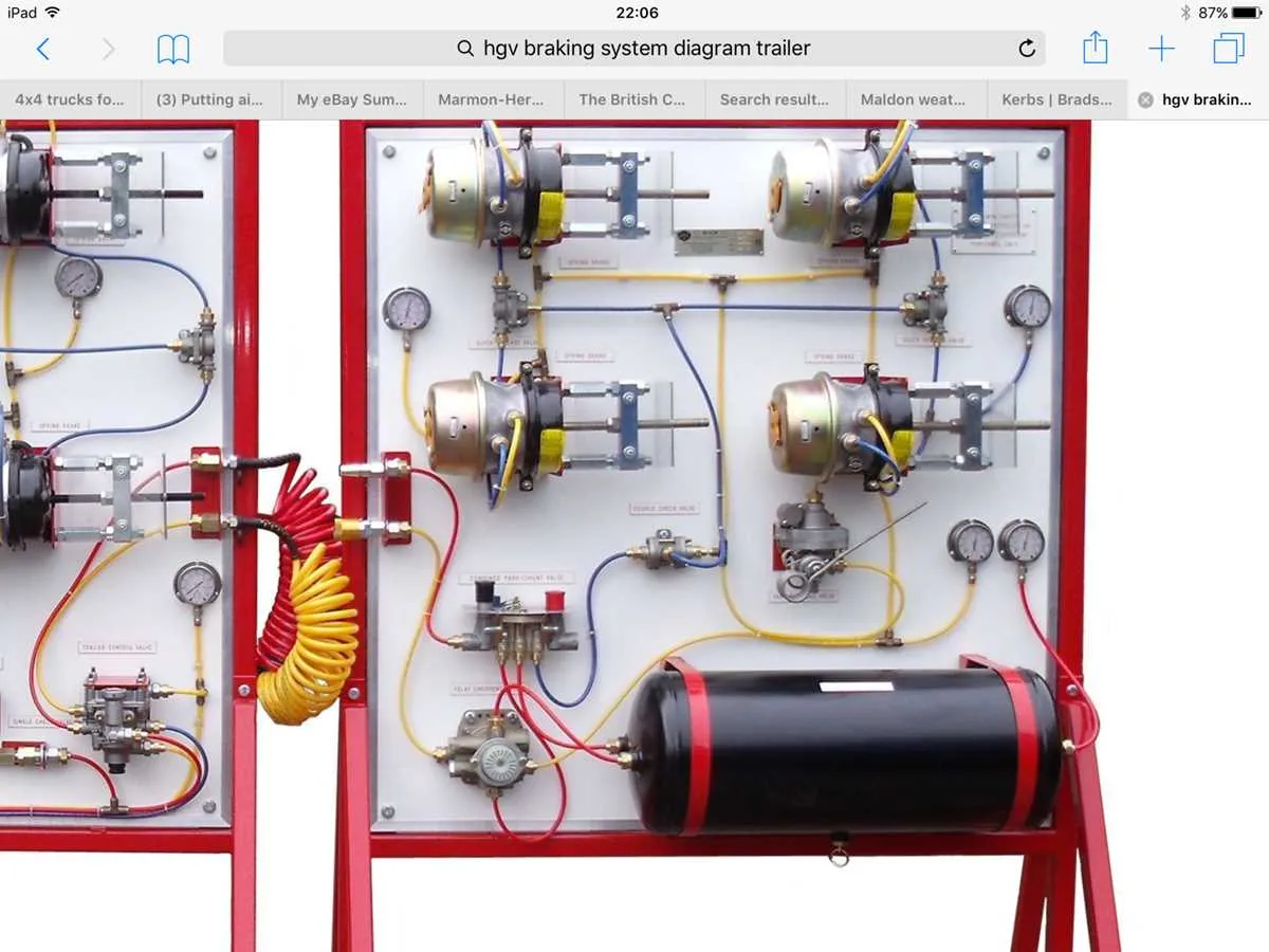
Ensure proper inspection and maintenance of the pneumatic stopping components to avoid failure during operation. The mechanism relies on compressed fluid to generate force that brings the vehicle to a halt, making it essential to monitor each part of the setup. Regular checks of the valve connections and reservoirs will help prevent leaks and ensure consistent performance.
Reservoirs store compressed air and release it when required. Ensure they are sealed tightly and free from damage. Regularly inspect for any signs of corrosion or wear that could compromise their functionality. Over time, moisture can accumulate, so ensure proper drainage systems are in place.
Control Valves regulate the fluid flow to the stopping units. A malfunctioning valve can result in insufficient force, rendering the stopping process ineffective. Test the valves periodically for responsiveness, and replace faulty parts promptly.
Understanding how the components interact with each other is key. Pressure reduction valves maintain safe operational pressures, while brake chambers exert the necessary force on the braking mechanism. These elements must be in top working condition for reliable stopping action. Replacing components based on their wear cycle is crucial to maintain high performance.
Understanding the Pneumatic Stopping Mechanism
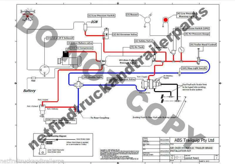
Ensure proper maintenance of the pneumatic circuits, as these are essential for safe operation. The pressure modulation components should be regularly checked for leaks or blockages, as this can impair functionality. Always verify that the valve regulating the flow is functioning correctly, as any malfunction here could cause delayed response times or system failure under stress.
The coupling points between the towing vehicle and the attached unit should be closely inspected to confirm that the connection is airtight. Any damage to hoses or fittings can compromise the performance of the entire setup. Pay particular attention to the quick-release valves and emergency brakes, as they are crucial for rapid stopping under emergency conditions.
Check the reservoirs frequently for any signs of water or contaminants. These can cause the internal components to seize or degrade over time. Clean filters regularly and replace any worn-out parts to ensure continued reliable operation. Additionally, monitor the pressure levels to confirm that they remain within the specified range to avoid unnecessary strain on the system.
Make sure the connections are secure and that no moisture accumulates in the tubing, as this could result in frozen or damaged components during colder months. Always follow the manufacturer’s guidelines for air compressor maintenance and ensure that all pressure relief valves are in optimal condition.
Examine the response times during tests to confirm that there is no noticeable delay in activation. If the stopping force does not engage as quickly as expected, it may indicate an issue with the pneumatic pressure or control valves. Immediate attention is required to prevent potential accidents.
Components of a Heavy-Duty Vehicle’s Pneumatic Stopping Mechanism
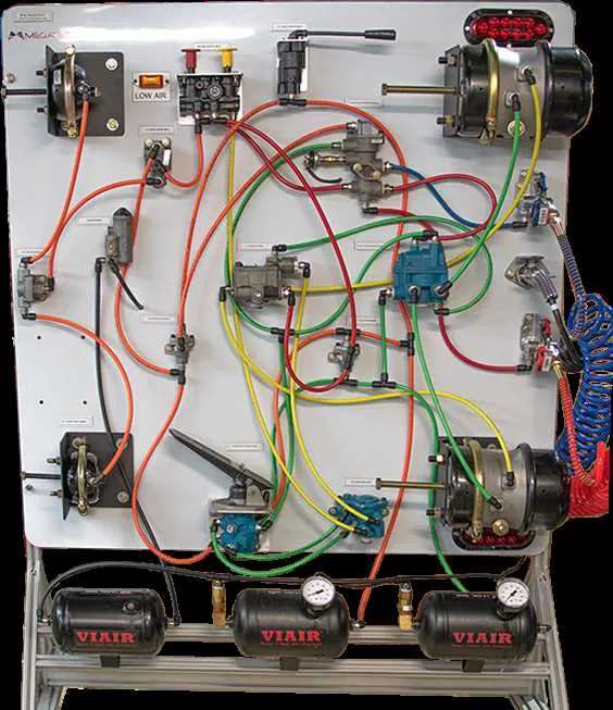
To ensure optimal performance, it is essential to regularly check the following key elements:
Compressor: The compressor pressurizes the reservoir, providing the necessary force for the entire setup. It’s crucial that the compressor functions smoothly and maintains the appropriate air pressure. A malfunction can lead to insufficient pressure, affecting the stopping efficiency.
Reservoir: The storage container holds pressurized air used in the operation of the brakes. Make sure to inspect it for leaks and cracks, which can cause air loss, compromising the braking force.
Control Valve: This valve regulates the flow of pressurized air to the braking components, ensuring that the pressure is applied correctly during stopping events. Regular cleaning and lubrication of the valve ensure its responsiveness and longevity.
Chambers: These units convert air pressure into mechanical force, pushing the brake linings against the drum or disc. It’s important to inspect the diaphragms for wear and check the seals for any leaks, as damaged chambers can lead to inconsistent braking performance.
Lines and Hoses: All connections between the compressor, reservoir, valves, and chambers are made through pneumatic lines and hoses. These components must be free of cracks or abrasions. Regularly check for any signs of wear, especially at connection points, to avoid air leaks that can reduce stopping power.
Relay Valve: The relay valve ensures that air pressure is delivered swiftly to the braking units when needed. If it malfunctions, it can cause delays in the application of braking force, which is dangerous in emergency situations. Regular testing is recommended to verify its functionality.
Spring Brake Mechanism: This mechanism is a safety feature that activates when the main air supply is lost. It’s essential to check that the spring system can engage properly and apply sufficient force in case of a failure in the primary braking system.
Understanding Flow Dynamics in the Pneumatic Stopping Mechanism
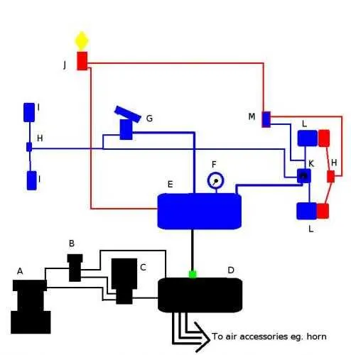
To optimize performance, ensure efficient distribution and control of pressure within the stopping mechanism. Follow these key practices:
- Ensure proper sealing in all valve connections to maintain consistent pressure levels.
- Inspect and maintain the compressor to prevent leaks that could disrupt the pressure flow.
- Check the condition of flexible hoses regularly to avoid blockages or ruptures.
Flow through the control circuit must remain unimpeded for effective activation. To achieve this:
- Ensure that valves are properly calibrated to control pressure transitions smoothly.
- Regularly clean or replace filters to prevent debris from clogging the pressure pathways.
Pressure build-up should be consistent throughout, particularly in the modulation section. Achieve this by:
- Verifying the proper function of the regulator, especially under load conditions.
- Adjusting the release mechanism to ensure pressure is maintained during deceleration.
For smooth operation and reliability, conduct periodic checks of all connections and components. Replace damaged parts promptly to maintain peak functionality.
Maintenance Tips for Trailer Air Brake Systems
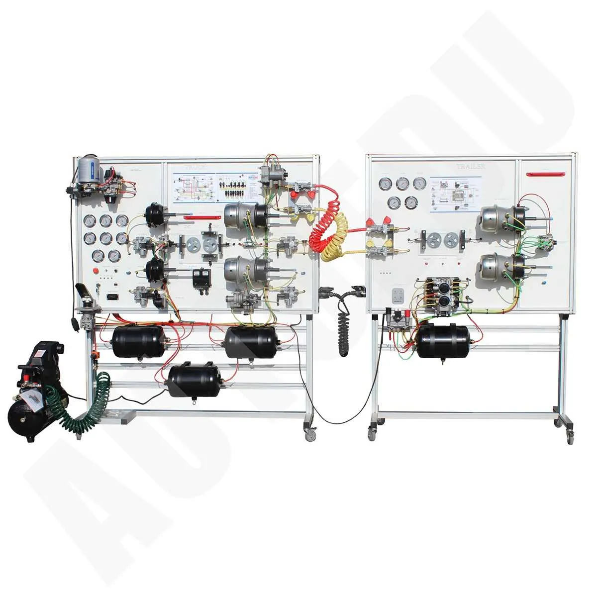
Regular inspection of the compressor is essential to ensure optimal pressure levels. Check the compressor’s performance every 6 months to identify early signs of wear or malfunction. If pressure drops below recommended levels, inspect for leaks in the hoses or connections, and replace any damaged components immediately.
Ensure the valves are functioning correctly by testing them under load. Faulty valves can cause uneven pressure distribution, leading to unreliable stopping performance. Lubricate moving parts regularly, and clean the valve openings to prevent dirt buildup, which can impair operation.
Verify that the reservoir tanks are free from moisture and condensation, as water can cause corrosion and freezing during colder months. Drain the tanks weekly, especially in regions with high humidity. Install moisture traps to filter excess water and keep the components in top condition.
Inspect all flexible lines for cracks, bulges, or signs of wear. Replace any damaged or deteriorated hoses immediately to prevent sudden failures that could compromise safety. Use high-quality rubber or synthetic materials for replacements to ensure durability and reliability.
Test the parking brake mechanism periodically to ensure it engages and releases smoothly. Over time, cables and linkage can stretch or seize, affecting performance. Lubricate the cable assembly to reduce friction and prevent rusting.
Perform regular checks on the pressure gauge to ensure accurate readings. Inaccurate gauges can mislead the driver about the system’s condition. If readings fluctuate or remain static despite pressure changes, replace the gauge without delay.