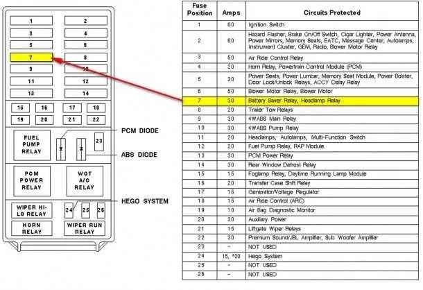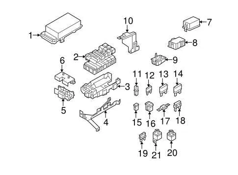
Start by checking the front power module beneath the hood, near the battery on the driver’s side. Lift the cover to reveal the grid of current protectors and relays. For the ignition coil circuit, refer to slot 29; for the A/C compressor clutch, examine position 15. Ensure the main engine relay is seated correctly in location 5 to avoid starting issues.
Inside the cabin, locate the secondary panel behind the kick panel on the passenger side. To access it, gently remove the trim cover. Circuit 33 controls the power windows, while slot 9 handles the radio unit. If the rear blower motor is unresponsive, inspect section 22.
Important: Always disconnect the negative battery terminal before replacing any blown elements to prevent short circuits. Use a 20A rating for the front wiper motor and a 15A for the lighter socket. Cross-reference the legend printed on the reverse side of the access cover for exact alignment.
Tip: When troubleshooting intermittent electrical faults, test the continuity across each terminal using a multimeter. Replace any components showing high resistance or corrosion at the contacts.
Main Relay Panel Layout

Locate the primary relay panel beneath the dashboard on the driver’s side. Start by identifying slot number 1, which controls the accessory delay. Adjacent to it, slot 2 is assigned to the memory module. Position 3 handles power seats, while 4 manages the adjustable pedals. Position 5 is linked to the climate control blower. Use a 15A mini-type for slots 3 and 5, and a 10A for 4.
Inside the passenger compartment, slot 6 is critical for the SYNC module. Slot 7 supports the steering column control module. Use a 7.5A insert for these positions. Avoid using higher amp ratings to prevent wire overheating. Panel access requires gently pulling the lower dash cover and using a needle-nose plier for tight slots.
Engine compartment power control center contains key elements: position 12 governs the cooling fan relay, 13 powers the ignition coil, and 14 is dedicated to the PCM. Each uses a 20A cartridge-style insert. Ensure these components are disconnected before removal to avoid short circuits. A diagram is typically printed on the inside of the cover for quick reference.
How to Locate the Interior and Engine Compartment Fuse Boxes in the 2013 Ford Flex
Start by accessing the cabin panel positioned beneath the steering column. Use a flathead screwdriver or your fingers to gently pry open the rectangular cover, which sits just above the brake pedal area. This panel conceals the main distribution point for interior electrical components.
- Driver-side kick panel: Pull back the trim slightly to gain full access.
- Cover may include a diagram on its reverse side–check for quick identification of circuits.
For the under-hood compartment, lift the bonnet and secure it with the prop rod. Locate the black rectangular enclosure mounted near the battery on the driver’s side, close to the windshield.
- Unclip the two latches on either side of the casing.
- Remove the lid to reveal the layout of high-amperage connections and relays.
- Refer to the molded schematic inside the lid for slot functions.
Always disconnect the negative battery cable before touching any terminal to prevent accidental shorts or injury.
Fuse Assignment and Amp Ratings for Each Circuit in the 2013 Ford Flex
Start by verifying the amperage before replacing any blown component. For the power windows, the slot marked F14 holds a 30A cartridge. The climate control blower motor uses position F22 with a 40A maxifuse. Rear defrost runs on location F15, also rated at 40A. F1 protects the starter relay with a 40A limit.
Power liftgate relies on position F18 and a 30A cartridge. Audio system components connect through slot F26 (20A mini). The electric power steering draws from F10 with a 5A micro. The memory seats and adjustable pedals share F17 at 30A. Cigarette lighter and front accessory ports use F20 and F21, each at 20A.
Headlamp relay is guarded via F12 with a 20A rating. High beams are split: left on F4 and right on F5, each with a 10A limit. Tail lamps are protected by F6 and F7, both at 10A. The fuel pump circuit is assigned to F8, rated at 20A. Heated mirrors are connected to F11 and require a 10A micro-type.
Steps to Safely Replace a Blown Fuse in the 2013 Ford Flex
Disconnect the negative battery cable before any electrical work to prevent shorts or accidental activation of circuits.
Open the panel located under the dashboard on the driver’s side or access the secondary module beneath the hood near the battery housing. Identify the damaged unit by inspecting each transparent element for a broken filament or discoloration.
Use needle-nose pliers or a plastic puller tool to remove the faulty component. Do not force it–if stuck, gently rock it side to side while pulling.
Match the amperage rating using the color-coded key or printed number on the original part. Never install one with a higher capacity, as this can cause overheating or component failure.
| Rating (Amps) | Color Code | Common Usage |
|---|---|---|
| 5 | Tan | Instrument Cluster, Audio Control |
| 10 | Red | Lighting System, Warning Indicators |
| 15 | Blue | Power Outlet, Wipers |
| 20 | Yellow | Door Locks, Seat Adjustment |
| 30 | Green | Cooling Fan, Power Windows |
Push the replacement fully into the socket until seated. Reconnect the battery cable and test the corresponding circuit immediately. If the new part fails again, inspect the wiring and associated devices for faults before attempting another substitution.