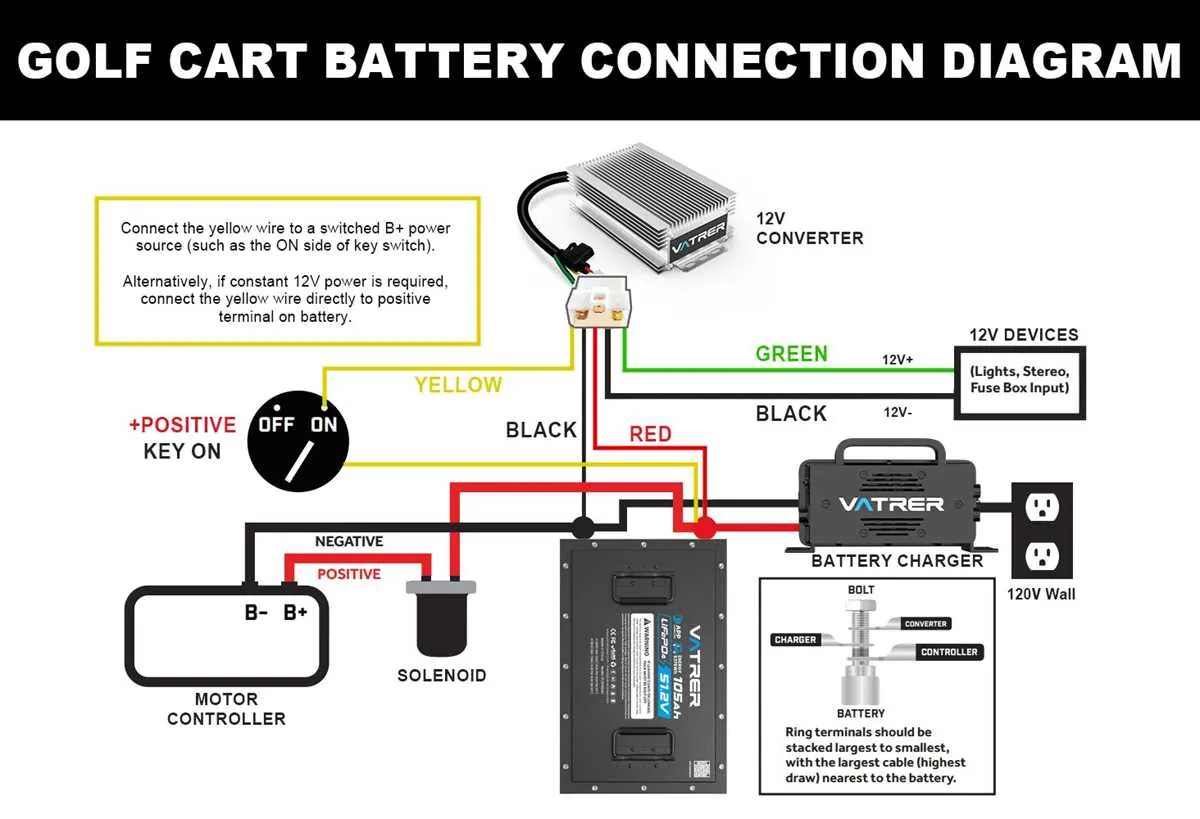
When servicing or upgrading a 48V golf cart, understanding the electrical connections is crucial. This includes identifying key components like the battery pack, motor controller, and the various switches that control the power flow. It’s essential to ensure proper connectivity to avoid malfunction or damage to the system.
First step: Start by inspecting the connections to the main power source. Typically, a series of six 8V batteries make up the 48V system. Each battery should be connected in series, with the negative terminal of one connected to the positive terminal of the next. Make sure these terminals are clean and free from corrosion.
Next: The motor controller regulates power to the drive system. Ensure all wire connections to the controller are secure, particularly the ground connection. A loose ground can cause the system to short out or function erratically. If the controller is malfunctioning, it might be necessary to reset or replace it.
For safety: Always disconnect the power source before working on the system to avoid electric shock or inadvertent short circuits. Use appropriate tools and double-check each wire for correct placement to avoid errors in the setup.
Following these steps will ensure your electric vehicle runs efficiently and avoids electrical issues down the road.
Electrical Setup for 48V Golf Cart
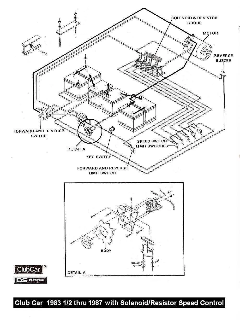
Start by ensuring all connections are tight and secure. Begin with the battery pack, connecting the positive and negative terminals to the respective cables. Pay close attention to the polarity, as reversing connections can cause serious damage.
The motor control unit should be connected properly to the battery terminals, with appropriate fuses in place to prevent overloads. Each wire must be routed according to the manufacturer’s specifications to avoid short circuits and ensure efficient power transfer. Use color-coded cables to distinguish between the various power lines.
For efficient operation, the controller should be connected to the throttle, brake, and reverse switch. Check that the controller is properly grounded to avoid any malfunction or erratic behavior in the system. Be sure that all connections are properly insulated to prevent corrosion, which can degrade the system’s performance over time.
To avoid power loss, use high-quality copper cables for all major connections. Ensure that the battery charger plug is in good condition and securely fastened to avoid disconnections during charging. Additionally, inspect the fuse box to verify that each fuse is correctly rated to handle the current for the different components.
Finally, perform a full system check by testing each component individually to ensure everything is working as expected. After confirming all parts are properly installed and operational, test the vehicle under normal conditions to ensure smooth and reliable performance.
How to Identify Key Components in the 48 Volt Club Car Wiring Diagram
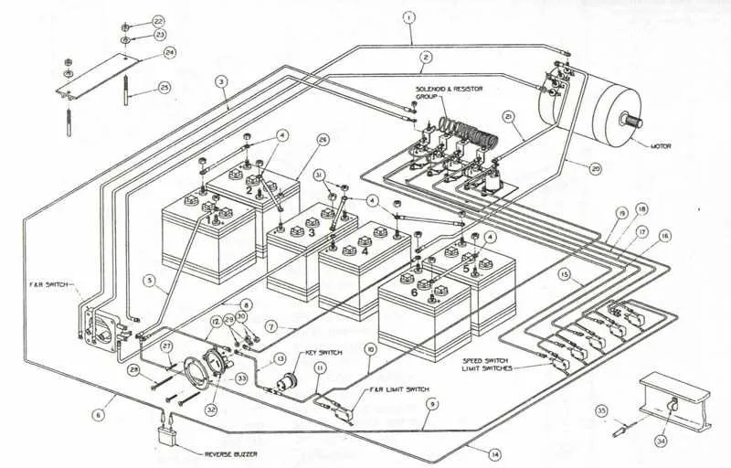
To effectively identify essential parts in the electrical layout, focus on the main elements: battery pack, motor, controller, and switches. Each component plays a critical role in system functionality and requires specific attention during troubleshooting.
Start with the battery connections, where positive and negative terminals are clearly marked. Ensure the polarity is correctly followed to avoid short circuits or improper operation. The battery pack is typically represented with bold lines, indicating high-current paths.
The motor connections are another focal point. These are usually found near the controller, and they connect the motor’s terminals to the circuit. Verify that the connections are solid and free from corrosion, as this can cause inefficient performance or failure.
Controllers act as the central hub, regulating power flow. The controller’s terminals are often linked to various control inputs, such as speed sensors and throttle switches. Examine the wiring to confirm no loose or frayed wires, which can lead to malfunction or erratic behavior.
Switches such as the key switch, forward/reverse switch, and throttle input play significant roles in controlling power distribution. Each switch should be checked for proper engagement and function, ensuring the system reacts correctly to user input.
Lastly, inspect the grounding points. A poor or loose ground can result in voltage drops, poor performance, or intermittent issues. Ground wires are typically connected to the frame, often highlighted in the layout for easy identification.
Step-by-Step Guide to Troubleshooting a 48 Volt Club Car Wiring Issue
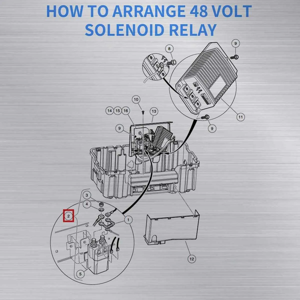
Begin by checking the battery connections. Ensure that all terminals are free of corrosion and tightly secured. Loose or corroded connections can cause power interruptions, leading to malfunctioning electrical components.
- Disconnect the batteries before inspecting the connections to avoid short circuits.
- Clean battery terminals using a wire brush and apply a protective coating to prevent future corrosion.
Next, examine the fuse box. Fuses are vital for protecting the system against power surges, and a blown fuse may be the reason for the failure. Replace any damaged fuses with the correct rating to avoid further issues.
- Locate the fuse box and identify the blown fuse.
- Use a multimeter to check continuity and confirm the fuse is faulty.
- Ensure the replacement fuse matches the specifications of the original fuse.
Inspect the controller unit. The controller governs the operation of electrical components, and any malfunction could stop power flow to essential systems.
- Test the controller with a diagnostic tool if available.
- Look for visible signs of wear, such as burned components or melted connections.
Check the power cables and connections leading to the motor. Over time, cables can wear out or become disconnected, causing poor performance or complete system failure.
- Inspect the power cables for signs of fraying, cuts, or other damage.
- Ensure connections are secure and free of dirt or rust that could impede the flow of electricity.
Finally, test the components individually. If you’re unable to locate the source of the issue, consider isolating parts like the throttle, speed sensor, or motor itself. By testing each component, you’ll narrow down the potential cause of the malfunction.
- Use a multimeter to test individual components for proper voltage and functionality.
- If any part is not functioning as expected, replace it with a compatible replacement part.
After identifying and fixing the issue, reassemble the system, reconnect the power, and perform a system test to confirm that all functions are working correctly.
Understanding the Connections for the 48-Cell Power System
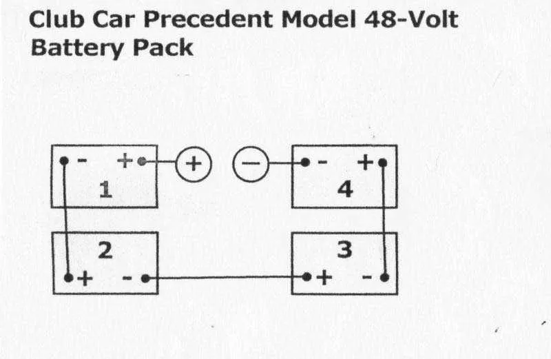
Ensure the battery pack is correctly positioned with its positive terminal on the right side and the negative terminal on the left. Properly connect each cell in a series to create a balanced circuit. The positive terminal from the first battery connects to the negative terminal of the second, continuing this sequence across the entire array.
The power feed cable should attach to the main terminal of the battery pack, while the return path links to the ground connection of the vehicle’s chassis. It’s important to check that each connection is tight, as loose terminals can cause heat buildup and energy loss.
The controller’s input terminals should receive the appropriate power from the main pack, with the negative side going to the ground. Always double-check the polarity before powering up to prevent short circuits or damage to sensitive components.
Each additional component, such as the motor or accessories, should be linked through dedicated relays that ensure current is only directed to the necessary sections when needed. Avoid overloading circuits by confirming the amperage ratings match the system requirements.
Use fuses or breakers at critical points to protect against surges or faults. These safety devices should be easily accessible for maintenance and inspection. Make sure to check that all wire gauges match the system’s current needs to minimize resistance and ensure efficient power flow.