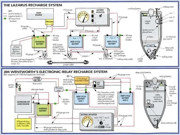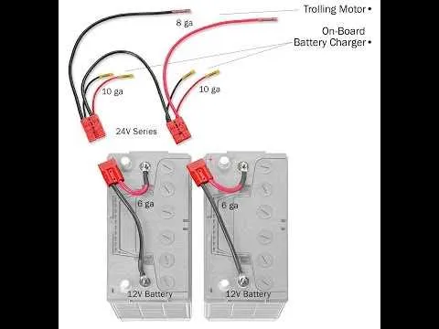
Start by ensuring that your power source can deliver the necessary amperage for the system. Use a 24V battery setup with a capacity suited to your needs, considering factors like usage time and power draw. A typical configuration includes two 12V batteries wired in series. This will provide the required 24V output.
Connect the positive terminal of the first battery to the negative terminal of the second one. This creates the series circuit, which doubles the voltage while maintaining the same amperage rating of a single 12V battery. Always ensure that the battery terminals are properly secured and that connections are tight to avoid power loss.
The negative terminal of the second battery connects to the grounding point of the system. The positive terminal from the first battery should link to the power input of the device. Use an appropriately rated fuse or circuit breaker between the battery and device to protect the system from overloads.
Use thick enough gauge wire for the connections, as too thin a wire can lead to significant voltage drops and inefficiency. 12 or 10 gauge wire is typically recommended, but check the manufacturer’s guidelines for specific requirements.
Double-check all connections before turning on the system to ensure everything is wired correctly. Properly sealed connectors help to prevent corrosion, which can weaken the system’s performance over time.
If you’re unsure about the configuration, consult a professional or refer to the manufacturer’s manual for more detailed instructions. Keeping the wiring clean and well-maintained will prolong the life and reliability of your setup.
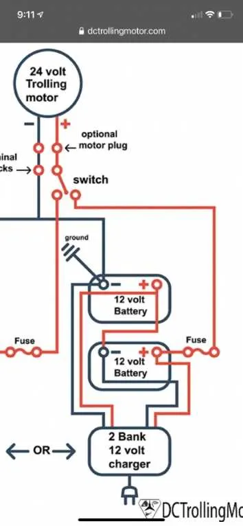
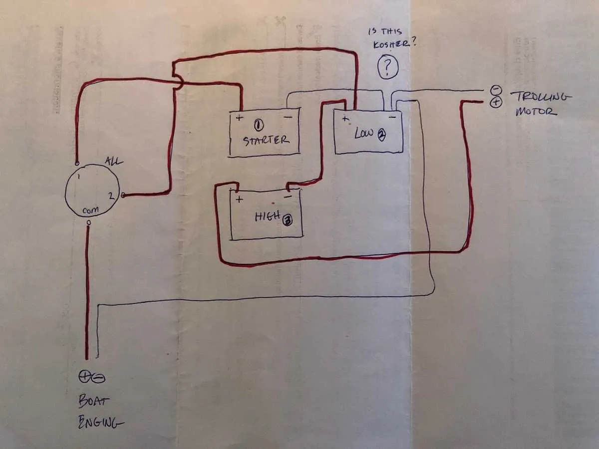
24 Volt Diagram Trolling Motor Wiring

To wire a 24-volt system for your boat, begin by ensuring you have two 12-volt batteries connected in series. This setup creates the required 24V output. Connect the positive terminal of the first battery to the negative terminal of the second. The remaining free positive and negative terminals will be your power supply, where the positive connects to the motor’s positive input and the negative terminal connects to the motor’s negative input.
When installing the battery terminals, use marine-grade connectors to prevent corrosion, and ensure the connections are tight to avoid power loss. Make sure to fuse the positive line near the battery to protect the system from overcurrent or short circuits.
Install a suitable switch that can handle 24V systems to control the motor’s on/off functionality. It is also essential to use thick gauge cables for power distribution, as the motor requires high amperage, especially at full throttle. Choose wires that can handle at least 10% more amperage than your motor’s maximum draw to ensure safe operation.
Consider using a battery isolator if you plan to use more than one set of batteries, allowing you to control charging and ensure the power system operates independently. Lastly, regularly check the connections and cables for wear, corrosion, or any signs of damage to maintain the integrity of the setup.
Choosing the Right Components for 24V Electric Propulsion System Setup
Start by selecting a deep-cycle battery designed for high demand. These batteries provide long-lasting power and are built to handle sustained use without significant degradation.
- Battery Capacity: Opt for a battery with at least 100Ah (Amp-Hour) capacity. This ensures enough energy for extended trips.
- Battery Type: AGM (Absorbent Glass Mat) or lithium batteries are ideal due to their reliability and maintenance-free nature.
- Marine-Rated Battery: Ensure the battery is specifically designed for marine use, as these are built to withstand the rigors of water exposure.
Next, focus on selecting an appropriate controller. The controller manages the power flow and ensures safe operation under different load conditions.
- Controller Compatibility: Ensure that the controller matches the system’s power requirements. A 24V system typically needs a controller rated for 48A or higher.
- Efficiency: Choose a high-efficiency controller that minimizes power loss, improving battery performance.
For the connections, use high-quality marine-grade cables with sufficient gauge to handle the current without excessive heat buildup.
- Cable Gauge: Use at least 6 AWG for the connection between the power source and the electric unit. For longer runs, consider 4 AWG to reduce resistance.
- Corrosion Resistance: All cables should have tinned copper conductors and marine-grade insulation to prevent corrosion.
Don’t forget about the fuse or circuit breaker. This acts as a safeguard, preventing potential damage in case of overload or short circuits.
- Fuse Rating: The fuse should be rated slightly higher than the expected maximum current draw. For a 24V system, a 60A fuse is typically suitable.
- Location: Install the fuse or circuit breaker near the power source to ensure protection right from the start of the power supply.
Finally, consider a battery monitor to keep track of the charge level and prevent deep discharge, which can shorten battery life.
- Battery Monitor Features: Look for models that provide real-time voltage, amperage, and remaining capacity information.
Step-by-Step Guide to Wiring a 24 Volt System

Start by preparing two 12V batteries. Connect them in series to create the necessary 24V power supply. Ensure that the positive terminal of the first battery connects to the negative terminal of the second one. The remaining free terminals will serve as the system’s power output: the positive terminal from the first battery and the negative terminal from the second.
Use appropriately rated cables for the setup. For the connection between the batteries, employ a thick gauge wire to handle the current efficiently. Secure the wires with high-quality connectors to avoid power loss or potential shorts.
Next, link the power output terminals from the batteries to the control unit, making sure to respect the polarity. The positive output from the first battery should go to the positive terminal of the control unit, and the negative terminal from the second battery to the negative terminal of the control unit.
Attach the output cables from the control unit to the propulsion unit. Double-check the polarity to ensure that the system will operate correctly. Use heat shrink tubing or electrical tape to secure and protect each connection, preventing corrosion and enhancing long-term reliability.
Test the system by powering it on and verifying the functionality of the control unit. Make adjustments to ensure smooth operation, and check all connections for any signs of loose contacts or power loss.
Troubleshooting Common Wiring Issues in 24 Volt Trolling Motors

Check for loose connections between the battery and the power unit. Secure all terminals and ensure that no corrosion has formed. Clean the contacts with a wire brush or a corrosion remover.
If the unit fails to run at full power, inspect the fuse box for blown fuses. Replace any damaged fuses with the correct amperage rating as per the specifications. Verify that the fuse type matches the system’s requirements.
Inspect the control switch for proper function. If it’s sticky or unresponsive, it could be worn out or dirty. Clean the switch, or replace it if necessary to restore functionality.
Examine the cables for signs of wear or damage, such as fraying or exposed wires. Repair or replace any damaged cables immediately to prevent short circuits.
Test the battery to ensure it is holding charge. If the power supply is weak, try charging it fully and check if the problem persists. A failing battery may need replacement if it does not hold charge despite being fully charged.
If the system shows intermittent power loss, consider checking the voltage drop across the entire circuit. Excessive resistance in the wires or connectors can cause inconsistent performance. Make sure all components are tightly connected and there is no rust or dirt build-up.
For further diagnosis, use a multimeter to check continuity and voltage levels throughout the circuit. This can help identify weak spots or areas with high resistance.